


Facsimile
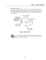
C) Replacing the PCNT board
The PCNT board stores the absorption amount of waste ink absorber and vertical
alignment data. Therefore, when replacing the PCNT board, print out the absorption
amount data and then enter this data into the new PCNT board, and then adjust vertical
alignment.
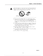
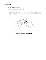
d) Precautions when attaching/ detaching the flat cable
Attaching or detaching the flat cable
the machine is turned ON may cause a short
in the connector, resulting in malfunction. Always turn the power OFF before attaching/
detaching the flat cable.
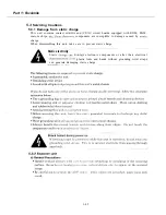
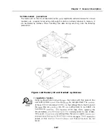
5.3.6
Opening the upper cover
A
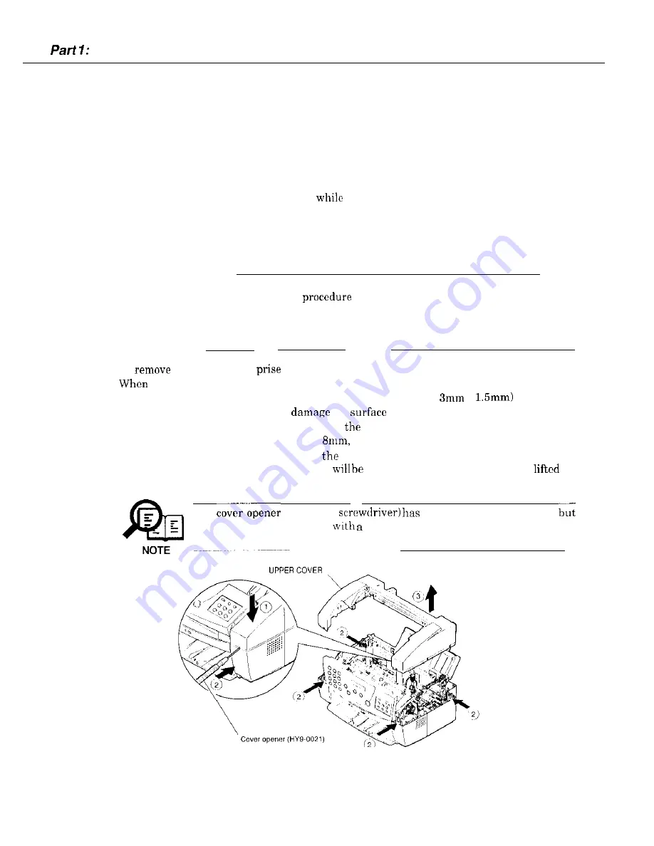
How to open the upper cover
Unless the correct
is followed when removing the upper cover,
the outer covers may be damaged, and the plastic claws may be broken.
Be sure to use the correct tools for the job. If any of the outer covers are
damaged during the work, they must be replaced with new ones.
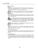
To
the upper cover,
loose the four tabs, using the tip of the recommended tool.
loosing these tabs, be careful of the following points.
l
Use a tool whose diameter is less than that of the holes. (hole:
X
Using larger diameter tools may
the
around the holes.
l
Be careful not to cause any damage around
boles.
l
Do not insert the tool any further than
otherwise the claws may be damaged.
*When loosing the claws, press down on
upper cover, insert the tool, and when the claw
is loose, raise the upper cover. The tabs
difficult to remove if the cover is
up
first.
The
(round-tip
been set as a special tool,
any precision screwdriver
tip diameter of 1.5 mm or less would do
instead. If using a substitute, be careful not to scratch any surfaces.
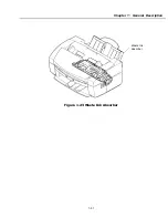
Figure 1-21 Opening the Upper Cover
l-46
Summary of Contents for C5000 - MultiPASS Color Inkjet Printer
Page 1: ...MultiPASS C5000 SERVICE MANUAL Canon ...
Page 5: ...REVISION I CONTENT 0 I Original ...
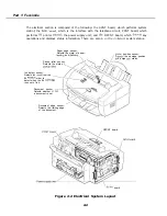
Page 26: ...Chapter 7 General Description 3 1 External View Front View Figure 1 3 External View 1 l 11 ...
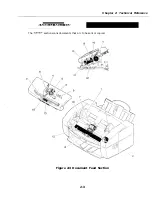
Page 27: ...Part 1 Facsimile Rear View Inside the Printer Cover Figure 1 4 External View 2 1 12 ...
Page 28: ...Part 7 Facsimile 3 2 Operation Panel The Operation Panel Document feed lever 0 0 0 0 1 14 ...
Page 34: ...Part 1 Facsimile ...
Page 36: ...Part 7 Facsimile r w Units mm r 0 4 0 0 Figure l 13 Dimensions l 22 ...
Page 65: ...Chapter 1 General Description Waste Ink absorber Figure 1 23 Waste Ink Absorber 1 51 ...
Page 92: ...Part 7 Facsimile Figure 2 18 Printing Signals HQ Mode 2 24 ...
Page 93: ...Chapter 2 Technical Refereno 6 1 Component Block Diagram Figure 2 19 Block Diagram 2 25 ...
Page 150: ...Part 1 Facsimile Figure 3 28 Print Pattern Sample 3 48 ...
Page 184: ...Part 1 Facsimile U Vertical alignment Correction l l l l 3 7 ...