


Chapter 2: Technical Reference
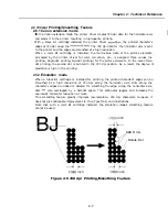
2.6 720
dpi Printing/Smoothing Feature
2.6.1 Canon extension mode
In
the Canon extension mode, the printer driver creates 720 dpi data for the horizontal axis
and sends it to the printer, resulting in high-quality printing.
With black BJ cartridge installed, the printer driver
the printed character’s
edges at 720 dpi along the
The 720 dpi data for the horizontal axis is sent
to the printer and the edges are smoothed at a high resolution.
When a color BJ cartridge is installed, the multi-value data of the picture elements
processed by the printer driver for color correction, etc., is assigned three values (no
printing, single-dot printing, two-dot printing) for the picture elements. In the
of two-
dot printing, the second dot is printed in the 720 dpi position. As a result, the degree of
gradation is high in the printing.
2.6.2
Emulation mode
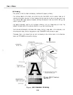
When a black BJ cartridge is installed for printing, the printed character’s edges can be
smoothed at a high resolution of 720 dpi along the horizontal axis. Dots along the
character’s edges are added or deleted for smoothing the edge. Along the horizontal axis,
dots
also overlapped by a half-dot space. This eliminates jaggies and increases the
equivalent horizontal resolution at twice.
This smoothing feature greatly improves low-resolution, 180 dpi characters. However, it
does not give noticeable improvement to True Type fonts and illustrations.
Note that with a color BJ cartridge installed, the emulation mode’s smoothing feature
cannot be used.
inch
Add
D o
,
Delete Dot
inch
inch
Figure 2-5 720 dpi Printing/Smoothing Feature
2-7
Summary of Contents for C5000 - MultiPASS Color Inkjet Printer
Page 1: ...MultiPASS C5000 SERVICE MANUAL Canon ...
Page 5: ...REVISION I CONTENT 0 I Original ...
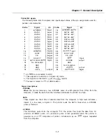
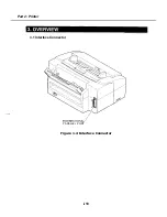
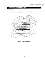
Page 26: ...Chapter 7 General Description 3 1 External View Front View Figure 1 3 External View 1 l 11 ...
Page 27: ...Part 1 Facsimile Rear View Inside the Printer Cover Figure 1 4 External View 2 1 12 ...
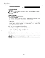
Page 28: ...Part 7 Facsimile 3 2 Operation Panel The Operation Panel Document feed lever 0 0 0 0 1 14 ...
Page 34: ...Part 1 Facsimile ...
Page 36: ...Part 7 Facsimile r w Units mm r 0 4 0 0 Figure l 13 Dimensions l 22 ...
Page 65: ...Chapter 1 General Description Waste Ink absorber Figure 1 23 Waste Ink Absorber 1 51 ...
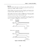
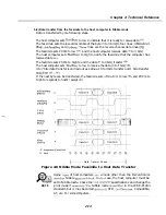
Page 92: ...Part 7 Facsimile Figure 2 18 Printing Signals HQ Mode 2 24 ...
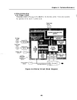
Page 93: ...Chapter 2 Technical Refereno 6 1 Component Block Diagram Figure 2 19 Block Diagram 2 25 ...
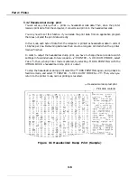
Page 150: ...Part 1 Facsimile Figure 3 28 Print Pattern Sample 3 48 ...
Page 184: ...Part 1 Facsimile U Vertical alignment Correction l l l l 3 7 ...