


Part 1: Facsimile
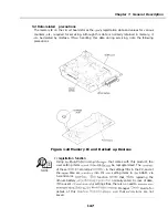
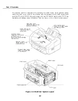
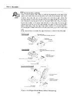
The electrical section is composed of the following: the SCNT board, which performs system
control; the NCU
which is the interface with the telephone circuit; PCNT board; which
performs
printer
the power supply unit; and
OPCNT board, which
key
operations and displays status information. There are also 6
system status.
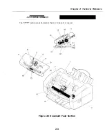
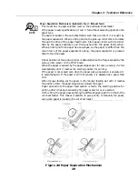
Paper edge sensor:
Detects the state of paper
and
Pickup roller sensor:
Detects the state of
position sensor:
the carriage position
d purge
status.
Ink detect sensor:
Detects ink
from the
BJ
order to
detect when the BJ
runs out of ink.
Document sensor
Detects whether
a document set.
Document edge sensor:
Detects the trailing edge
of the document.
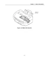
OPCNT board
board
Figure 2-2 Electrical System Layout
2-2
Summary of Contents for C5000 - MultiPASS Color Inkjet Printer
Page 1: ...MultiPASS C5000 SERVICE MANUAL Canon ...
Page 5: ...REVISION I CONTENT 0 I Original ...
Page 26: ...Chapter 7 General Description 3 1 External View Front View Figure 1 3 External View 1 l 11 ...
Page 27: ...Part 1 Facsimile Rear View Inside the Printer Cover Figure 1 4 External View 2 1 12 ...
Page 28: ...Part 7 Facsimile 3 2 Operation Panel The Operation Panel Document feed lever 0 0 0 0 1 14 ...
Page 34: ...Part 1 Facsimile ...
Page 36: ...Part 7 Facsimile r w Units mm r 0 4 0 0 Figure l 13 Dimensions l 22 ...
Page 65: ...Chapter 1 General Description Waste Ink absorber Figure 1 23 Waste Ink Absorber 1 51 ...
Page 92: ...Part 7 Facsimile Figure 2 18 Printing Signals HQ Mode 2 24 ...
Page 93: ...Chapter 2 Technical Refereno 6 1 Component Block Diagram Figure 2 19 Block Diagram 2 25 ...
Page 150: ...Part 1 Facsimile Figure 3 28 Print Pattern Sample 3 48 ...
Page 184: ...Part 1 Facsimile U Vertical alignment Correction l l l l 3 7 ...