


Chapter 2: Technical Reference
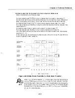
b-2) Data transfer from the facsimile to the host computer In Nibble mode
Data is transferred by
following steps.
The host computer sets
to low to indicate that it is ready to receive data
The facsimile sets the low-order nibble of the byte to 3 bits) to four lines:
Xflag,
and
lines are the reverse channel data lines.)(Q).
The facsimile sets PtrClk to low
and the host computer receives data to 3 bits).
The host computer sets
to high to notify the facsimile that the computer has
received data
The facsimile sets PtrClk to high to end the data to 3 bits) transfer
The host computer sets
to low to receive the data (4 to bits)
4 to 7 bits data transfer is carried out as same as 0 to 3 bits transfer and 1 bite transfer
If the next byte can be transferred, the facsimile sets
to low
and PtrClk to
High to responds to host’s receipt
PtrClk
P
Data Transfer Phase
Figure 2-6 Nibble Mode Facsimile to Host Data Transfer
NOTE
Some
of host computers
a mode other than the Bi-Centronics
Nibble
In
case, the host computer must be
set to Nibble mode. Check the
specifications and change the
print mode if
Nibble mode is
in the IEEE-P1284
standard, but it may be called
STD,
Compatible,
AT, etc. For some computers.
2-13
Summary of Contents for C5000 - MultiPASS Color Inkjet Printer
Page 1: ...MultiPASS C5000 SERVICE MANUAL Canon ...
Page 5: ...REVISION I CONTENT 0 I Original ...
Page 26: ...Chapter 7 General Description 3 1 External View Front View Figure 1 3 External View 1 l 11 ...
Page 27: ...Part 1 Facsimile Rear View Inside the Printer Cover Figure 1 4 External View 2 1 12 ...
Page 28: ...Part 7 Facsimile 3 2 Operation Panel The Operation Panel Document feed lever 0 0 0 0 1 14 ...
Page 34: ...Part 1 Facsimile ...
Page 36: ...Part 7 Facsimile r w Units mm r 0 4 0 0 Figure l 13 Dimensions l 22 ...
Page 65: ...Chapter 1 General Description Waste Ink absorber Figure 1 23 Waste Ink Absorber 1 51 ...
Page 92: ...Part 7 Facsimile Figure 2 18 Printing Signals HQ Mode 2 24 ...
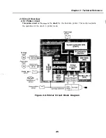
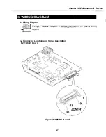
Page 93: ...Chapter 2 Technical Refereno 6 1 Component Block Diagram Figure 2 19 Block Diagram 2 25 ...
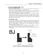
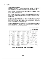
Page 150: ...Part 1 Facsimile Figure 3 28 Print Pattern Sample 3 48 ...
Page 184: ...Part 1 Facsimile U Vertical alignment Correction l l l l 3 7 ...