


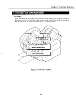


Chapter 2: Technical Reference
2.3
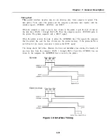
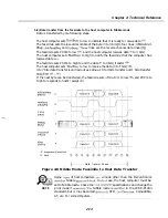
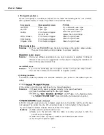
Data Flow
1)
Interface
Character codes, control codes, and image data conforming to the printer’s character table
are sent to the interface from the computer. The data are received when the printer is in
on-line standby, or when the carriage changes directions during printing.
2)
Input
buffer
Data received from the interface are stored in the printer DRAM’s built in input (reception)
buffer
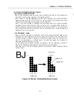
3) Data
analysis and printer buffer
The
MPU analysis the data stored in the input buffer, and printing image data for each
nozzle of the
cartridge are stored in the printer DRAM’s built-in print buffer.
If there are character data, the
ROM font image data
stored in the print
buffer. Control codes are used for switching print modes, etc. The image data are already
formatted for each nozzle of the BJ cartridge, and
stored as is in the print buffer.
4) Printing
When control codes with a
etc, print start function are processed, and the print
buffer becomes full, the image data stored in the printer buffer are sent to the
cartridge
and printed out.
Character Code:
= 42 Hex.
Character Code: “J”
4A
Hex
Control Code: ESC
(Select Image
Mode)
Hex.
Hex
cd>
(DRAM)
Character “BJ”
Image
Figure 2-2 Data Flow (image)
2-3
Summary of Contents for C5000 - MultiPASS Color Inkjet Printer
Page 1: ...MultiPASS C5000 SERVICE MANUAL Canon ...
Page 5: ...REVISION I CONTENT 0 I Original ...
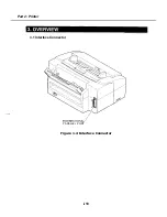
Page 26: ...Chapter 7 General Description 3 1 External View Front View Figure 1 3 External View 1 l 11 ...
Page 27: ...Part 1 Facsimile Rear View Inside the Printer Cover Figure 1 4 External View 2 1 12 ...
Page 28: ...Part 7 Facsimile 3 2 Operation Panel The Operation Panel Document feed lever 0 0 0 0 1 14 ...
Page 34: ...Part 1 Facsimile ...
Page 36: ...Part 7 Facsimile r w Units mm r 0 4 0 0 Figure l 13 Dimensions l 22 ...
Page 65: ...Chapter 1 General Description Waste Ink absorber Figure 1 23 Waste Ink Absorber 1 51 ...
Page 92: ...Part 7 Facsimile Figure 2 18 Printing Signals HQ Mode 2 24 ...
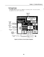
Page 93: ...Chapter 2 Technical Refereno 6 1 Component Block Diagram Figure 2 19 Block Diagram 2 25 ...
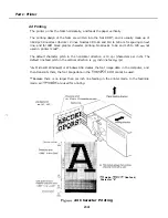
Page 150: ...Part 1 Facsimile Figure 3 28 Print Pattern Sample 3 48 ...
Page 184: ...Part 1 Facsimile U Vertical alignment Correction l l l l 3 7 ...