


Part 2:
Printer
Page
Chapter 1: General Description
l - 4
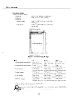
Figure 1 Printing Range
Figure 2 Signal Circuits
9
Figure 3 Interface Timing
1 -10
Figure 4 Interface Connector
3
4
5
7
2 -13
Chapter 2: Technical Reference
Figure
Printer Outline
Figure
2 Data Flow (image)
Figure
3 Character Printing
Figure
4 Printer Circuit Block Diagram
Figure
5 720 dpi Printing/Smoothing Feature
Figure 6 Nibble Mode Facsimile to Host Data Transfer
6
7
Chapter 3: Maintenance Service
Figure
Hexadecimal Dump Print (Sample)
Figure
2 SCNT Board
2
3
Chapter 4: Appendix
Figure 1 Location for the Printer
Figure 2 Connecting the Interface Cable
Summary of Contents for C5000 - MultiPASS Color Inkjet Printer
Page 1: ...MultiPASS C5000 SERVICE MANUAL Canon ...
Page 5: ...REVISION I CONTENT 0 I Original ...
Page 26: ...Chapter 7 General Description 3 1 External View Front View Figure 1 3 External View 1 l 11 ...
Page 27: ...Part 1 Facsimile Rear View Inside the Printer Cover Figure 1 4 External View 2 1 12 ...
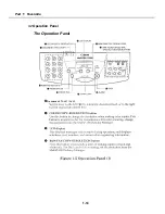
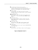
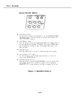
Page 28: ...Part 7 Facsimile 3 2 Operation Panel The Operation Panel Document feed lever 0 0 0 0 1 14 ...
Page 34: ...Part 1 Facsimile ...
Page 36: ...Part 7 Facsimile r w Units mm r 0 4 0 0 Figure l 13 Dimensions l 22 ...
Page 65: ...Chapter 1 General Description Waste Ink absorber Figure 1 23 Waste Ink Absorber 1 51 ...
Page 92: ...Part 7 Facsimile Figure 2 18 Printing Signals HQ Mode 2 24 ...
Page 93: ...Chapter 2 Technical Refereno 6 1 Component Block Diagram Figure 2 19 Block Diagram 2 25 ...
Page 150: ...Part 1 Facsimile Figure 3 28 Print Pattern Sample 3 48 ...
Page 184: ...Part 1 Facsimile U Vertical alignment Correction l l l l 3 7 ...