


1 -53
-54
-54
1 -54
1 -55
1 -55
-56
1 -56
1 -57
1
3
6
2 -11
2 -18
2 -18
2 -21
2 -23
2 -25
2 -25
2 -26
2 -29
2 -32
2 -32
2 -32
2 -32
2 -33
2 -33
2 -33
2 -34
2 -34
2 -34
2 -35
1
2
2
2
3
5.5
5.4.5 Data initialization through service operation
Protective Mechanism
55.1 Data battery backup function
5.5.2 BJ cartridge maintenance features
5.53 Heat protection mechanism
5.5.4 Overcurrent protection
5.5.5 Lightning protection
5.56 Power leakage protection
6. QUALIFICATION REQUIRED FOR INSTALLATION WORK
Chapter 2: Technical Reference
2.
3.
4.
5.
6.
COMPONENT LAYOUT
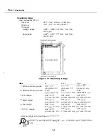
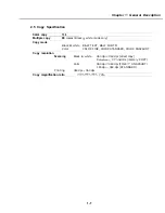
SCANNER MECHANISM
PAPER SUPPLY MECHANISM
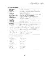
PRINTER SECTION
BJ CARTRIDGE
5.1 Structure
5.2 BJ Head Driver Block Diagram
5.3 Printing Signal
ELECTRIC CIRCUIT
6.1 Component Block Diagram
6.2 Circuit Board Components
6.3 Flow of Image Signals
COMMUNICATION SYSTEM OPERATIONS
7.1 FAX/TEL Switching
7.1 Settings
7.1.2 Parameters
7.2 Answering Machine Connection
Settings
7.2.2 Parameters
NEW FUNCTION
8.1 Color Scanning Ability
8.1 Contact sensor specifications
Reading color documents
Chapter 3: Maintenance
Service
MAINTENANCE LIST
1.1
Consumables
1.2 Cleaning
1.3 Periodic Inspection
1.4
Replacement Parts
1.5 Adjustment Items
1.6 General Tools
V
Summary of Contents for C5000 - MultiPASS Color Inkjet Printer
Page 1: ...MultiPASS C5000 SERVICE MANUAL Canon ...
Page 5: ...REVISION I CONTENT 0 I Original ...
Page 26: ...Chapter 7 General Description 3 1 External View Front View Figure 1 3 External View 1 l 11 ...
Page 27: ...Part 1 Facsimile Rear View Inside the Printer Cover Figure 1 4 External View 2 1 12 ...
Page 28: ...Part 7 Facsimile 3 2 Operation Panel The Operation Panel Document feed lever 0 0 0 0 1 14 ...
Page 34: ...Part 1 Facsimile ...
Page 36: ...Part 7 Facsimile r w Units mm r 0 4 0 0 Figure l 13 Dimensions l 22 ...
Page 65: ...Chapter 1 General Description Waste Ink absorber Figure 1 23 Waste Ink Absorber 1 51 ...
Page 92: ...Part 7 Facsimile Figure 2 18 Printing Signals HQ Mode 2 24 ...
Page 93: ...Chapter 2 Technical Refereno 6 1 Component Block Diagram Figure 2 19 Block Diagram 2 25 ...
Page 150: ...Part 1 Facsimile Figure 3 28 Print Pattern Sample 3 48 ...
Page 184: ...Part 1 Facsimile U Vertical alignment Correction l l l l 3 7 ...