


Part Facsimile
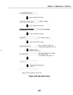
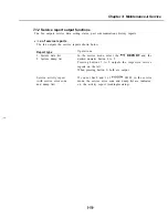
b) Operation panel tests
The operation panel test is selected by pressing the 7 button from the faculty test menu.
In this test, check that the display, LED lamps, and buttons on the control panel are
operating correctly.
b-l) Display test
Pressing the
S T A R T / C O P Y
button from the control panel menu,
is displayed 16
characters by 1 line on the display. The next time the
START/COPY
button is pressed,
all the LCD dots on the display are displayed. Check for any LCD dots in the display
that are not displayed.
b-2) LED lamp test
The LED lamp test is selected by pressing the
START/COPY
button after the display
test.
When the
S T A R T / C O P Y
button is pressed, all the lamps on the control panel light.
Check for any LED that does not light during the test.
b-3) Operation button test
The Operation button test is selected by pressing the
S T A R T / C O P Y
button after the
LED lamp test.
In this test, you press the button corresponding to the displayed character to put it out.
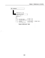
The table giving the
between the characters and the buttons is below.
button
Character
Numeric buttons
Color-copy-resolution button
&
B W FAX/COPY-resolution button
R
button
F
Function button
D
Coded dial button
C
Cartridge button
M
Resume button
When all the characters displayed have
out, the system next starts the one-touch
speed dialing button
letters a-f are displayed on the display, corresponding to
one-touch speed dialing buttons
Each letter displayed on the display goes out
when its corresponding one-touch speed dialing button is pressed.
In this test, check for operation buttons whose corresponding character or letter does not
go out when the button is prcsscd.
3-54
Summary of Contents for C5000 - MultiPASS Color Inkjet Printer
Page 1: ...MultiPASS C5000 SERVICE MANUAL Canon ...
Page 5: ...REVISION I CONTENT 0 I Original ...
Page 26: ...Chapter 7 General Description 3 1 External View Front View Figure 1 3 External View 1 l 11 ...
Page 27: ...Part 1 Facsimile Rear View Inside the Printer Cover Figure 1 4 External View 2 1 12 ...
Page 28: ...Part 7 Facsimile 3 2 Operation Panel The Operation Panel Document feed lever 0 0 0 0 1 14 ...
Page 34: ...Part 1 Facsimile ...
Page 36: ...Part 7 Facsimile r w Units mm r 0 4 0 0 Figure l 13 Dimensions l 22 ...
Page 65: ...Chapter 1 General Description Waste Ink absorber Figure 1 23 Waste Ink Absorber 1 51 ...
Page 92: ...Part 7 Facsimile Figure 2 18 Printing Signals HQ Mode 2 24 ...
Page 93: ...Chapter 2 Technical Refereno 6 1 Component Block Diagram Figure 2 19 Block Diagram 2 25 ...
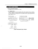
Page 150: ...Part 1 Facsimile Figure 3 28 Print Pattern Sample 3 48 ...
Page 184: ...Part 1 Facsimile U Vertical alignment Correction l l l l 3 7 ...