


3
4
4
4
4
4
4
4
4
6
6
7
3 -10
3 -14
3 -14
3 -15
3 -15
3 -19
3 -26
3 -26
3 -27
3 -29
3 -31
3 -31
3 -31
3 -31
3 -32
3 -33
3 -40
3 -41
3 -43
3 -43
3 -43
3 -44
3 -44
3 -45
3 -46
3 -46
3 -47
3 -49
3 -52
3 -57
3 -57
1.7 Special Tools
2. HOW TO CLEAN PARTS
2.1 Main Unit Outer Covers
2.2 Separation Roller
2.3 Document Feed/Eject Roller
2.4 Separation Guide
2.5 Scanning Glass (Contact Sensor)
2.6 White Sheet
2.7 Printer Platen
3. ADJUSTMENT
3.1 CS LED Lights-on Duration Adjustment
3.2 Vertical Alignment Correction
3.3 Head Gap Adjustment
4. TROUBLESHOOTING
4.1 Troubleshooting Index
4.2 Errors Shown on the Display
4.2.1 User error message
4.2.2 Error codes
4.3 Errors not Shown on the Display
4.3.1 General errors
4.3.2 Printing problem
4.3.3 Scanning problem
5. SERVICE SWITCHES
5.1 Hardware Switches
5.2 Service Data
5.2.1 Service data overview
5.22 Service data registration/setting method
5.2.3 Service data setting
5.2.4 Explanation of service data
5.2.5 New
added to this model
6. TEST FUNCTIONS
6.1
User Test Print Functions
6.1 Nozzle check
6.2 Service Test Functions
6.2.1 Test mode overview
6.2.2 Test mode flowchart
6.2.3 D-RAM tests
6.2.4 CS tests
6.2.5 PRINT test
6.2.6 Modem and NCU tests
6.2.7 Faculty tests
7. SERVICE REPORT
7.1 Report Output Function
VI
Summary of Contents for C5000 - MultiPASS Color Inkjet Printer
Page 1: ...MultiPASS C5000 SERVICE MANUAL Canon ...
Page 5: ...REVISION I CONTENT 0 I Original ...
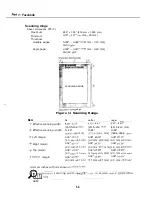
Page 26: ...Chapter 7 General Description 3 1 External View Front View Figure 1 3 External View 1 l 11 ...
Page 27: ...Part 1 Facsimile Rear View Inside the Printer Cover Figure 1 4 External View 2 1 12 ...
Page 28: ...Part 7 Facsimile 3 2 Operation Panel The Operation Panel Document feed lever 0 0 0 0 1 14 ...
Page 34: ...Part 1 Facsimile ...
Page 36: ...Part 7 Facsimile r w Units mm r 0 4 0 0 Figure l 13 Dimensions l 22 ...
Page 65: ...Chapter 1 General Description Waste Ink absorber Figure 1 23 Waste Ink Absorber 1 51 ...
Page 92: ...Part 7 Facsimile Figure 2 18 Printing Signals HQ Mode 2 24 ...
Page 93: ...Chapter 2 Technical Refereno 6 1 Component Block Diagram Figure 2 19 Block Diagram 2 25 ...
Page 150: ...Part 1 Facsimile Figure 3 28 Print Pattern Sample 3 48 ...
Page 184: ...Part 1 Facsimile U Vertical alignment Correction l l l l 3 7 ...