


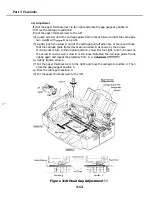


Part 1: Facsimile
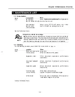
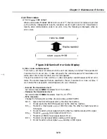
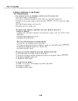
4.1 Troubleshooting Index
For troubleshooting, use the troubleshooting index below to investigate the cause of the
problem and refer to the specified page for countermeasures.
Problem
l
General errors
Page 3-26.
l
The unit does not power on. (Evaluation criteria: Look at the unit in question.)
l
The display
abnormal. (Evaluation criteria: Check it with the operation
l
The keys do not work.
criteria: Check it with the operation panel test.)
. No sound from the speaker
l
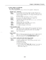
Errors shown on the display
criteria: Look at the
in question.)
.
The error message can be checked.
Page
3-15.
l
The error code can be checked.
Page 3-19.
l
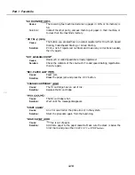
Printing problem (Evaluation criteria: Test printing Is no good.)
l
The paper is not fed properly.
Page
3-27.
The paper feed motor does not run.
The paper is not picked up from the auto sheet feeder.
l
The printing operation is abnormal.
Page
3-27.
Nothing is printed.
The carriage motor does not run.
l
Printing quality error
Page
3-26.
(Evaluation criteria: Look at the printing result.)
Print is not
Blurred or smudged characters.
Smudges appear
back of printed page.
Irregular print quality.
Print head needs cleaning.
Horizontal white stripes appear on
entirely black parts of the print.
l
Scanning problem (Evaluation criteria: Test printing is good, but the copied image is
no good.)
The document is not fed.
The document feed motor does not run.
The document slips against the rollers.
The document does not
Faulty scanner
sensors
l
The scanning image is
Nothing is
Page 3-29.
Page
3-30.
image hns vertical stripes.
The image has thick
contains black dots.
The color or brightness of the scanned image is not normal.
3-14
Summary of Contents for C5000 - MultiPASS Color Inkjet Printer
Page 1: ...MultiPASS C5000 SERVICE MANUAL Canon ...
Page 5: ...REVISION I CONTENT 0 I Original ...
Page 26: ...Chapter 7 General Description 3 1 External View Front View Figure 1 3 External View 1 l 11 ...
Page 27: ...Part 1 Facsimile Rear View Inside the Printer Cover Figure 1 4 External View 2 1 12 ...
Page 28: ...Part 7 Facsimile 3 2 Operation Panel The Operation Panel Document feed lever 0 0 0 0 1 14 ...
Page 34: ...Part 1 Facsimile ...
Page 36: ...Part 7 Facsimile r w Units mm r 0 4 0 0 Figure l 13 Dimensions l 22 ...
Page 65: ...Chapter 1 General Description Waste Ink absorber Figure 1 23 Waste Ink Absorber 1 51 ...
Page 92: ...Part 7 Facsimile Figure 2 18 Printing Signals HQ Mode 2 24 ...
Page 93: ...Chapter 2 Technical Refereno 6 1 Component Block Diagram Figure 2 19 Block Diagram 2 25 ...
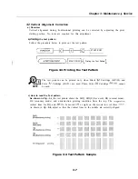
Page 150: ...Part 1 Facsimile Figure 3 28 Print Pattern Sample 3 48 ...
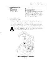
Page 184: ...Part 1 Facsimile U Vertical alignment Correction l l l l 3 7 ...