


Part 1: Facsimile
c-2) Adjustment
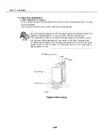
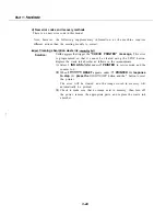
(1)
Set the paper thickness lever to the right and place the gap gauge at position B.
Move the carriage to position B.
(3) Set the paper thickness lever to the left.
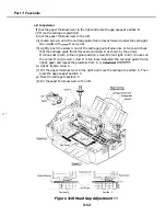
(4) Loosen screw A until the carriage guide frame moves forward under the carriage’s
own weight with
B as a pivot.
(5) Lightly push the screw A end of the carriage guide frame once or twice and check
that the carriage guide frame moves around screw B as shown by the arrows.
If it does not return to the original position, screw B is too tight. And if it moves on
the screw B end as well, screw B is too loose. Refasten the carriage guide frame
lightly again and repeat the procedure from C- 1)
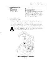
Adjustment
Lightly tighten screw A.
(7) Put the paper thickness lever to the right and move the carriage to position A. Then
place the gap gauge at position C.
Move the carriage to position C.
(9) Put the paper thickness lever to the left.
Position
Position C
Figure 3-10 Head Gap Adjustment
3-12
Summary of Contents for C5000 - MultiPASS Color Inkjet Printer
Page 1: ...MultiPASS C5000 SERVICE MANUAL Canon ...
Page 5: ...REVISION I CONTENT 0 I Original ...
Page 26: ...Chapter 7 General Description 3 1 External View Front View Figure 1 3 External View 1 l 11 ...
Page 27: ...Part 1 Facsimile Rear View Inside the Printer Cover Figure 1 4 External View 2 1 12 ...
Page 28: ...Part 7 Facsimile 3 2 Operation Panel The Operation Panel Document feed lever 0 0 0 0 1 14 ...
Page 34: ...Part 1 Facsimile ...
Page 36: ...Part 7 Facsimile r w Units mm r 0 4 0 0 Figure l 13 Dimensions l 22 ...
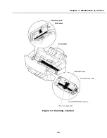
Page 65: ...Chapter 1 General Description Waste Ink absorber Figure 1 23 Waste Ink Absorber 1 51 ...
Page 92: ...Part 7 Facsimile Figure 2 18 Printing Signals HQ Mode 2 24 ...
Page 93: ...Chapter 2 Technical Refereno 6 1 Component Block Diagram Figure 2 19 Block Diagram 2 25 ...
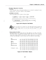
Page 150: ...Part 1 Facsimile Figure 3 28 Print Pattern Sample 3 48 ...
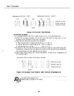
Page 184: ...Part 1 Facsimile U Vertical alignment Correction l l l l 3 7 ...