


Chapter General Description
5.4.2
Data in the control processing memory
is backed up by a lithium battery. It can retain the stored data for 5 years after the
power is turned off.
stores the following data: All the data the user entered with the
menu system, the activity reports and other report-generating data, the redial data
containing the redial destinations set with the Redial key, the servicing data set by repair
personnel with the service soft switch, and the CS LED lights-on duration data. SRAM
stores almost all of the data which can be entered or set.
These stored data can be checked with various reports.
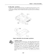
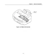
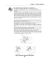
Jumper plug precautions
The control/image processing memory is backed up by shorting the jumper
pin
on the SCNT board with the jumper plug. If the the jumper plug
NOTE
is removed and the power is turned off, the data in SRAM will be lost.
Before removing the jumper plug, be
to print out the data stored in the
SRAM.
Lithium battery life
The lithium battery can last for over 5 years after the power is turned off.
When the power is on, the lithium battery’s power is untapped. Therefore,
the actual battery life can much longer.
When the lithium battery becomes exhausted,
“DATA ERROR”
will be
displayed after the power is turned off or on. When this happens,
the lithium battery. Since the data in SRAM will be lost when the battery
is replaced, it cannot be printed out.
After the lithium battery is replaced and the power is turned on,
“DATA
ERROR”
will be displayed. Press the
START/COPY
key to discard the
contents in SRAM and initialize it to the factory defaults.
Refer to Chapter 3: 3.7 CS
LED
duration adjustment on Page 3-6
to
reset the CS LED lights-on duration.
l - 4 9
Summary of Contents for C5000 - MultiPASS Color Inkjet Printer
Page 1: ...MultiPASS C5000 SERVICE MANUAL Canon ...
Page 5: ...REVISION I CONTENT 0 I Original ...
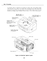
Page 26: ...Chapter 7 General Description 3 1 External View Front View Figure 1 3 External View 1 l 11 ...
Page 27: ...Part 1 Facsimile Rear View Inside the Printer Cover Figure 1 4 External View 2 1 12 ...
Page 28: ...Part 7 Facsimile 3 2 Operation Panel The Operation Panel Document feed lever 0 0 0 0 1 14 ...
Page 34: ...Part 1 Facsimile ...
Page 36: ...Part 7 Facsimile r w Units mm r 0 4 0 0 Figure l 13 Dimensions l 22 ...
Page 65: ...Chapter 1 General Description Waste Ink absorber Figure 1 23 Waste Ink Absorber 1 51 ...
Page 92: ...Part 7 Facsimile Figure 2 18 Printing Signals HQ Mode 2 24 ...
Page 93: ...Chapter 2 Technical Refereno 6 1 Component Block Diagram Figure 2 19 Block Diagram 2 25 ...
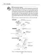
Page 150: ...Part 1 Facsimile Figure 3 28 Print Pattern Sample 3 48 ...
Page 184: ...Part 1 Facsimile U Vertical alignment Correction l l l l 3 7 ...