


Part 1: Facsimile
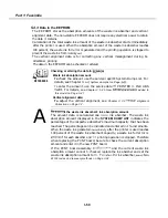
5.4.3
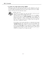
Data in the EEPROM
The EEPROM stores the absorption amounts of the waste ink absorber and vertical
alignment data. The non-volatile EEPROM does not require any electrical power to retain
the data it contains.
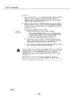
Calculation of the total waste ink amount of the waste ink absorber starts immediately
after the printer is used. When the absorption amount of the waste ink absorber reaches
100 percent, the waste ink full error is generated and the printing operation is stopped to
prevent the waste ink from
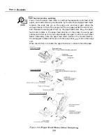
The vertical alignment data is for correcting any vertical misalignment during bi-
directional printing.
The data in the EEPROM can be checked or altered.
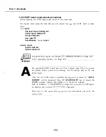
REFERENCE
A
Checking or altering the data In
Waste ink absorption amount:
To
check the amount, use the service report’s System Dump List. For
details, see Chapter 3.
a-2) System dump list on Page
To
enter the amount, use the service data PRINTER 3. INK ABS
For details, see
Chapter 3: 5.25 New
added to
this mode/ on Page 3-4 1.
Vertical alignment data:
To
adjust the vertical alignment, see
Chapter 3: 3.2
Alignment
Correction on Page 3-7.
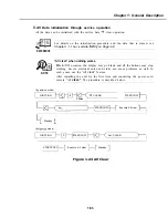
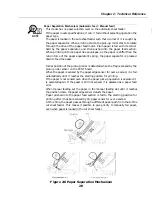
the waste ink absorber’s ink absorption amount.
The amount data is calculated one
ink absorber. The waste ink
absorption amount displayed in the
SYSTEM DUMP LIST
indicates the
percentage of the respective absorber’s maximum capacity that has been
reached. The percentage can be indicated and entered in 1% increments.
When the waste ink generated
after the printer is used reaches
100 percent of the waste ink absorber’s capacity, a waste ink full error is
for each absorber and
printing operation is stopped. Therefore
when replacing the PCNT board, be sure to check the current absorption
amount and enter it in the new PCNT board.
If the PCNT board assembly
and the current waste ink
absorption amount cannot checked, replace the ink absorber and set the
waste ink absorption amount to
To
thr ink absorber,
error
codes and recovery mefhods on Page 3-24.
l-50
Summary of Contents for C5000 - MultiPASS Color Inkjet Printer
Page 1: ...MultiPASS C5000 SERVICE MANUAL Canon ...
Page 5: ...REVISION I CONTENT 0 I Original ...
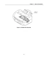
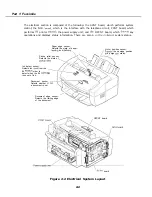
Page 26: ...Chapter 7 General Description 3 1 External View Front View Figure 1 3 External View 1 l 11 ...
Page 27: ...Part 1 Facsimile Rear View Inside the Printer Cover Figure 1 4 External View 2 1 12 ...
Page 28: ...Part 7 Facsimile 3 2 Operation Panel The Operation Panel Document feed lever 0 0 0 0 1 14 ...
Page 34: ...Part 1 Facsimile ...
Page 36: ...Part 7 Facsimile r w Units mm r 0 4 0 0 Figure l 13 Dimensions l 22 ...
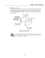
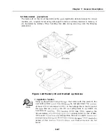
Page 65: ...Chapter 1 General Description Waste Ink absorber Figure 1 23 Waste Ink Absorber 1 51 ...
Page 92: ...Part 7 Facsimile Figure 2 18 Printing Signals HQ Mode 2 24 ...
Page 93: ...Chapter 2 Technical Refereno 6 1 Component Block Diagram Figure 2 19 Block Diagram 2 25 ...
Page 150: ...Part 1 Facsimile Figure 3 28 Print Pattern Sample 3 48 ...
Page 184: ...Part 1 Facsimile U Vertical alignment Correction l l l l 3 7 ...