Backplane pin
Description
AnInC
When used as current input (not on NY4130)
AnGND
GND
Tab. 13-10:
Analog inputs assignment
AnGND
12 k
W
100 k
W
120
W
VIN+
VIN-
[See Note 1 and 2]
[See Note 4]
Application
Node
[See Note 3]
AnInC
AnIn
+
AnIn
-
12 k
W
100 k
W
(
*
)
(
*
)
(
*
)
(
*
) See specific drive module for component value.
(
*
)
AnVref
10 nF
18
W
REF3112
+ 5V
-
+
2
100 nF
10 µF
100 nF
DGND
OPA2277
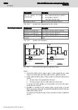
Fig. 13-10:
Analog input circuit for AnIn0 and AnIn1
Notes
1. The shielding does not have to be separate for each input as the
drawing suggests, but may be common for all analog signals in the
cable.
2. Follow the following cabling instructions.
●
Always use a shielded cable.
●
The shielding on the NYCe 4000 side of the cable must be
connected to Shield (house connector).
●
If the equipment on the application side is metal, connect the shield
to the equipment housing.
3. Connect the NYCe 4000, a power supply or other equipment on a metal
frame or mounting base and make sure there is a galvanic contact.
4. AnGND is connected to the internal system ground, which is ground
MCU, drive logic, encoder ground, and host PC if the MCU is NY4110
and an IEEE 1394b cable is used.
For proper use, this ground may not be connected to motor or digital I/O
ground.
5. AnVref can be used as a reference voltage for improved accuracy of
analog conversion.
6. If the encoder input source provides a balanced differential signal, it
may be desirable to connect a termination resistor between the signal
wires at the NYCe 4000 side. Consult for this the installation instructions
of the supplier.
NYCe 4000 Multi-axis motion control system Hardware Sys‐
tem Manual
171/233
Encoders
R911337671_Edition 18 Bosch Rexroth AG


