[See Note 1]
SN65HVD485
120
W
680 pF
DGND
330 pF
330 pF
A
B
EncGND
D
[See Note 3]
MAX1562
ON
Enc5V
[See Note 2]
+5V25
Dig5VIn -
NY4120 / NY4140
+5V25
Node
200
W
Enc
+
-
MAX1564
ON
Enc5V
EncGND
Enc
200
W
[See Note 3]
NY4125
100pF
+ 5V25
DGND
Node
SN65HVD485
A
B
[See Note 2]
[See Note 1]
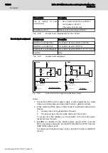
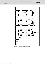
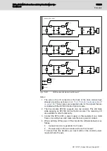
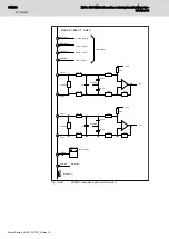
Fig. 13-15:
Input circuit for the Rexroth MSM absolute encoder
Notes
1. Connect the NYCe 4000, a power supply or other equipment on a metal
frame or mounting base and make sure there is a galvanic contact.
2. When switching off the power of the encoder the software behavior is as
follows.
●
A power loss error is generated on the axis.
●
The axis will go to the error state and be set 'not homed'.
To recover from this situation, you must switch on the encoder power,
reset and home the axis.
3. EncGND is connected to the internal system ground, which is ground
MCU, drive logic, analog I/O, and host PC if the MCU is NY4110 and an
IEEE 1394b cable is used.
For proper use, this ground may not be connected to motor or digital I/O
ground.
Encoder connection
Encoder type M0
For connection of Rexroth MSM encoder type M0 to the NYCe 4000, use
encoder cable RKG0040, order number R911328668, see
encoder type M0 cable layout" on page 179
and
type M0 cable pinout" on page 180
. These cables are custom made to the
length specified. The encoder cable RKG0040 connects the and
Battery– pins of the encoder to Enc5V and EncGND pins of the NYCe 4000
encoder power supply source.
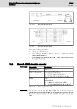
Fig. 13-16:
MSM encoder type M0 cable layout
NYCe 4000 Multi-axis motion control system Hardware Sys‐
tem Manual
179/233
Encoders
R911337671_Edition 18 Bosch Rexroth AG


