●
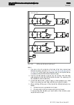
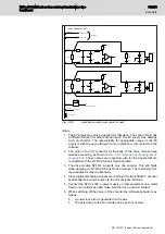
A power loss error is generated on the axis.
●
The axis will go to the error state and be set 'not homed'.
To recover from this situation, you must switch on the encoder power,
reset and home the axis.
3. EncGND is connected to the internal system ground, which is ground
MCU, drive logic, analog I/O, and host PC if the MCU is NY4110 and an
IEEE 1394b cable is used.
For proper use, this ground may not be connected to motor or digital I/O
ground.
Follow these cabling instructions.
●
Always use a shielded cable.
●
The shielding on the NYCe 4000 side of the cable must be connected to
Shield (house connector).
●
If the equipment on the application side is metal, connect the shield to
the equipment housing.
13.11 SinCos encoder
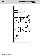
To connect the SinCos encoder to a drive module you must install the
NY4199 SinCos Option module on the drive module. See
"NY4199 SinCos Option module for SinCos based encoders" on page 200
for detailed information.
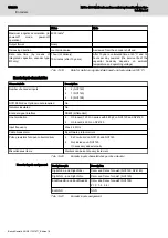
Power supply
Characteristic
Specification
Main power supply
5.25 V, ± 0.1 V
Switch off capability
Yes, switch on/off by software (see note 4)
●
NY4120
switch on/off per drive
●
NY4125, NY4130, NY4140
switch on/off per axis
Tab. 13-32:
Power supply characteristics
Encoder inputs characteristics
Characteristic
Description
Number of encoder inputs
●
2 (NY4120, NY4130)
●
1 (NY4140)
NY4199 SinCos Option module
required
Yes
Galvanic insulated
No
Encoder signal interface
The differential signal levels on sine signal and
differential signal levels on cosine signal are 1 Vtt.
The absolute value is in the range of 0 V to 5 V.
The index threshold value can be tuned by the
software or by using the tools, refer to software
and tools user manuals.
Increasing direction
Clockwise, as viewed form the encoder shaft end
Tab. 13-33:
Encoder inputs characteristics
188/233
Encoders
NYCe 4000 Multi-axis motion control system Hardware Sys‐
tem Manual
Bosch Rexroth AG R911337671_Edition 18


