Node Hiperface Axis1
120 Ohm
220 pF
220 pF
EncGND
10 Ohm
1 nF
10 Ohm
+ 2V5
4K99
4K99
20K
+
-
20K
SN65HVD485
120
Ohm
680 pF
DGND
330 pF
330 pF
A
B
Di
Dig5VIn1b-
FDC6324
ON/OFF
Enc8V
Di
Dig5VIn0b-
Di
Data+ (axis 1)
Data- (axis 1)
Cos
120 Ohm
220 pF
220 pF
EncGND
10 Ohm
1 nF
10 Ohm
+ 2V5
4K99
4K99
20K
+
-
20K
SN65HVD485
120
Ohm
680 pF
DGND
330 pF
330 pF
A
B
Di
Dig5VIn1a-
Sin
EncGND
[See Note 4]
[See Note 5]
[See Note 7]
[See Note 1 and Note 6]
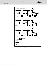
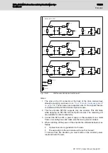
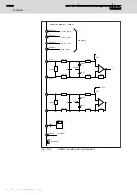
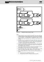
Fig. 13-29:
Hiperface encoder input circuit for axis1
Notes
1. The 8V supply may only be applied for Hiperface. The same I/O pin has
a different function for other encoder types. The 8V supply may damage
such an encoder. The responsibility for appropriate usage of the 8V
supply is with the user, although some protection is incorporated in the
software.
2. The pins on the I/O connector at the back of the drive module have
already a meaning, as shown in
tab. 13-44 "Encoder inputs assignment"
. These names are respected, also for the signals that are
connected with the NY4199 SinCos Option module.
3. The drive module NY4140 supports only one encoder. This still holds
while applying an NY4199 SinCos Option module. The remaining I/O’s
are available for other functionality.
4. Since digital and analog signals are combined for the EnDat2.1 encoder
special attention must be given to the risk of signal distortion.
5. Connect the NYCe 4000, a power supply or other equipment on a metal
frame or mounting base and make sure there is a galvanic contact.
6. When switching off the power of the encoder the software behavior is as
follows.
●
A power loss error is generated on the axis.
●
The axis will go to the error state and be set 'not homed'.
NYCe 4000 Multi-axis motion control system Hardware Sys‐
tem Manual
199/233
Encoders
R911337671_Edition 18 Bosch Rexroth AG


