The choice between the voltage or current measurement of the analog inputs
is user selectable by a software parameter, see the file "nhiparameters.h",
parameter NHI_PAR_ANINx_ADC_DIMENSION_SLOTy (x=0,1 y=0…4) and
the
NYCe
4000
Software
Reference
Manual,
enumeration
nhi_adc_dimension.
●
+ / – 10 Volt differential
If the analog input source provides a balanced differential signal,
connect the signal wires to the corresponding input pins on the
NYCe 4000 side.
●
+ / – 10 Volt single ended
If the encoder input source provides a single ended signal, connect the
signal wire to the positive input pin on the NYCe 4000 side, and connect
the application ground to the negative input pin on the NYCe 4000 side.
●
4 – 20 mA (not on NY4130)
●
Connect pin AnIn– to AnGND in the connector
●
Connect pin AnIn+ to AnInC in the connector
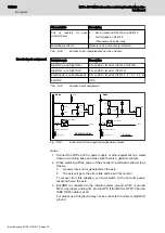
fig. 13-11 "How to connect the analog inputs" on page 172
shows how to
connect the analog inputs.
AnInC
AnGND
AnIn
+
AnIn
-
Node
Appplication
AnInC
AnGND
Application
ground
AnIn
+
AnIn
-
Node
Appplication
AnInC
AnGND
AnIn
+
AnIn
-
Node
Appplication
4 – 20 mA
See Note 5
+/- 10 Volt Differential
+/- 10 Volt Single ended
Fig. 13-11:
How to connect the analog inputs
13.7
Rexroth MSM incremental encoder
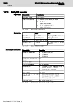
Power supply
Characteristic
Specification
Main power supply
5.25 V ± 0.1 V
Switch on/off capability
Yes, switch on/off by software
●
NY4120 : switch on/off per drive
●
NY4125, NY4140 : switch on/off per axis
Battery
No battery
Tab. 13-11:
Power supply characteristics
Encoder data
This encoder provides relative indirect position detection.
●
After power-on or a power supply failure, the axis must always be
moved to its home position before processing can begin.
●
The Rexroth MSM encoder counts downward (position increases) when
the shaft of the encoder rotates clockwise. This behavior is opposite to
most other encoders.
172/233
Encoders
NYCe 4000 Multi-axis motion control system Hardware Sys‐
tem Manual
Bosch Rexroth AG R911337671_Edition 18


