frequency is 8 kHz and the PVL frequency is 32 kHz, 4 complete PVL cycles
are executed in a single MCU sample. This aspect is important to remember
when you examine trace data, as trace data is gathered once per MCU
sample.
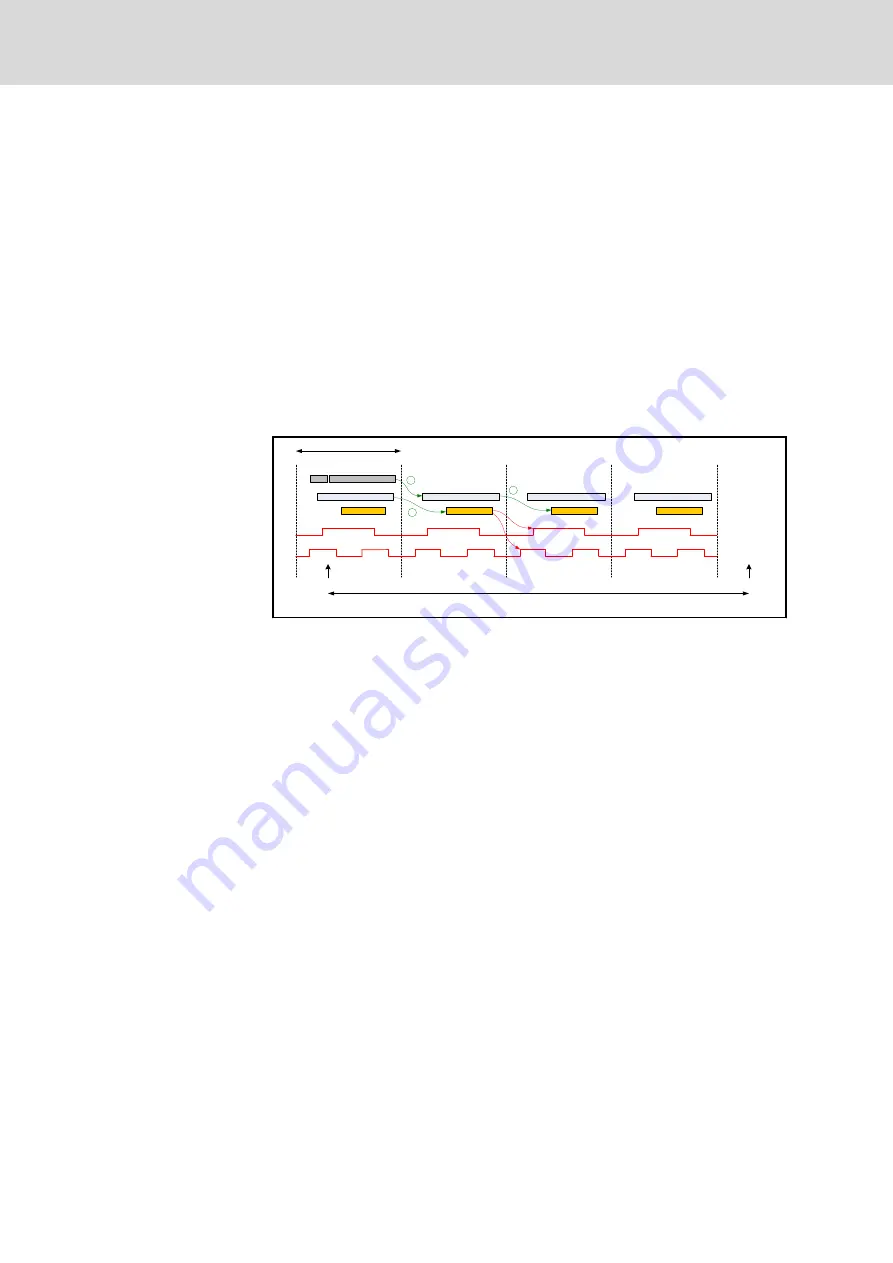
If a drive module includes a Current Control Loop (CCL), PVL results, for
example Controller Out, are input data for the CCL. The CCL is executed
concurrently with the PVL on the drive module. This implies that information
for the CCL is one CCL sample delayed if the PVL runs on the drive module,
see
fig. 13-5 "Timing relation of PVL sample, CCL sample and PWM signal"
If the PVL runs on the MCU, the information for the CCL is two PVL samples
delayed, because the PVL result (on the MCU) must be communicated to the
PVL on the drive module and the PVL on the drive module subsequently
must send the data to the CCL, see
fig. 13-5 "Timing relation of PVL sample,
CCL sample and PWM signal" on page 162
PVL (on MCU)
sync
latch
MCU sample
latch
latch
latch
32 kHz (31.25 µs)
latch
MCU sample
MCU sample (node) frequency 8 kHz (125 µs)
PVL (on drive)
CCL
CCL
CCL
CCL
PWM 32 kHz
PWM 64 kHz
1
2
PVL (on drive)
PVL (on drive)
PVL (on drive)
2
Fig. 13-5:
Timing relation of PVL sample, CCL sample and PWM signal
Likewise, the update of the PWM output is concurrently executed with the
CCL. The update of the PWM may be delayed one CCL sample depending
on the PWM frequency, see
fig. 13-5 "Timing relation of PVL sample, CCL
sample and PWM signal" on page 162
. The figure also shows that the CCL
result on the PWM signal will be effective earlier if the PWM frequency is set
higher.
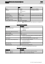
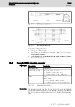
The CCL frequency can be set at 4, 8, 16, or 32 kHz. The PWM frequency
can be set to 16, 32, 64 or 96 kHz. Regarding the frequencies, the following
rule must be met in a node
f
node
£
f
PVL
£
f
CCL
£
f
PWM
To minimize delay times it is beneficial to execute the PVL, CCL, and PWM
processes at the highest possible frequency. However, the choice of
frequencies depends on other factors as well.
Encoder position data
As can be seen in
fig. 13-2 "Relation of MCU sample, PVL sample and
encoder data (PVL on drive @ 32 kHz)" on page 160
and
relation of MCU sample, PVL sample, encoder information (PVL on MCU)"
, the position information of SinCos-based encoders (SinCos,
EnDat2.1 and Hiperface) and quadrature encoders is available when the
sync packet transmission is started. The position information that the PVL (on
the drive module or on the MCU) uses is always the actual data of the
SinCos, EnDat2.1, Hiperface encoder or quadrature encoder.
162/233
Encoders
NYCe 4000 Multi-axis motion control system Hardware Sys‐
tem Manual
Bosch Rexroth AG R911337671_Edition 18


