5. If the analog equipment on the application side only accepts a single-
ended signal (not recommended), the accuracy of the analog signal may
be influenced by the resistor R* mentioned in Note 4. For this reason a
low value is chosen.
6. Connect the NYCe 4000, a power supply or other equipment on a metal
frame or mounting base and make sure there is a galvanic contact.
7. For proper use, this ground may not be connected to motor or digital I/O
ground
11.9
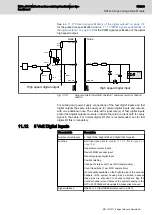
Digital Inputs
Characteristic
Description
Number of digital inputs
8, divided in 2 groups:
●
DigIn0 ... DigIn3 with DigComm0
●
DigIn4 ... DigIn7 with DigComm1
Functions
General Purpose Digital input
●
24V Hall sensors can be connected to the digital
inputs
–
DigIn0, DigIn1, Digin2 for axis0
●
Position latching
●
Change of state events (1 per MCU time
sample)
●
Count transitions interval (1 per MCU time
sample)
●
DigIn6 can be defined as disable drive input for
axis0
Disable drive functionality is defined through the
function SacWriteParameter, see NYCe 4000
Software User Manual.
The power amplifier is disabled after the disable drive
input is detected active for approximately 500 µs.
High and low side switching Possible (in groups of 4 digital inputs)
Galvanic insulated
Yes
Switch time (Filter delay)
Typical 100 μs
Permitted input voltage
–30 V ... +30 V
Input high level
15 V ... +30 V and –15 V ... –30 V
Input low level
–5 V ... +5 V
Input current @ 24V
Nominal 3,5 mA
Jitter on switching times
Typical 20 μs
Tab. 11-7:
Characteristics of the digital inputs
134/233
NY4140: High Voltage Drive Module
NYCe 4000 Multi-axis motion control system Hardware Sys‐
tem Manual
Bosch Rexroth AG R911337671_Edition 18


