13
Encoders
13.1
Introduction
This chapter describes how to connect different types of encoders to the
drive modules and gives timing information for the control loop of the various
drive modules. You can connect the following encoder types.
●
Quadrature encoder
●
Analog position sensor (not supported on NY4125)
●
Rexroth MSM incremental position encoder (not supported on NY4130)
●
Rexroth MSM absolute position encoder (not supported on NY4130)
●
Sanyo Denki absolute position encoder (not supported on NY4130)
●
EnDat2.2 encoder
●
SinCos based encoder types through an additional NY4199 SinCos
Option module (not supported on NY4125), see also
"NY4199 SinCos Option module for SinCos based encoders" on page
–
SinCos encoder
–
EnDat2.1 encoder
–
Hiperface encoder
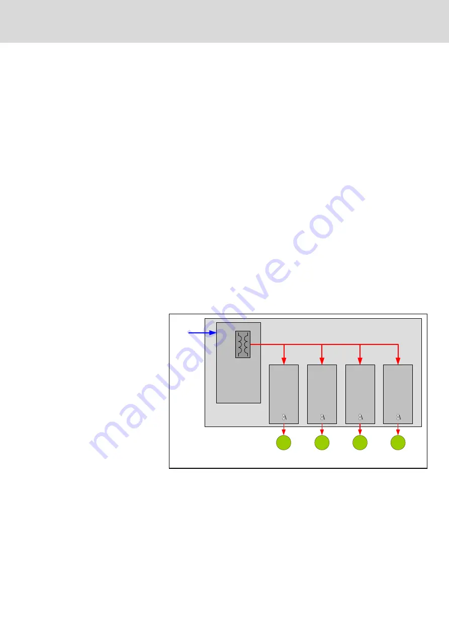
The power supply for all encoders connected to the drive modules in a
system housing is integrated on the MCU.
MCU
NY411x
NY4130
NY4140
NY4125
NY4120
24V SYSTEM
system housing
encoder
power supply
5.25 V max. 3 A
max 2
encoders
max 2
encoders
max 1
encoder
max 5
encoders
ENC
ENC
ENC
ENC
Fig. 13-1:
Power supply diagram for encoders
The encoder power supply on the MCU delivers a voltage of 5.25V at a
maximum of 3A. Thus, the total current of all encoders connected to a node
must be lower than 3A. Another limitation is the maximum current that a drive
module can deliver. The maximum current that a drive module can supply to
its connected encoders depends on the drive module.
NYCe 4000 Multi-axis motion control system Hardware Sys‐
tem Manual
157/233
Encoders
R911337671_Edition 18 Bosch Rexroth AG


