See
tab. 11-9 "Pulse time specifications of the digital outputs" on page 137
for the pulse time specification and
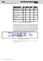
tab. 11-10 "PWM signal specifications of
the digital outputs" on page 138
for the PWM signal specification of the digital
high speed output.
Node
FastOut
GND_DIO
PTC
fuse
BSP250
BC847
BC847
1k
24V_DIO
High speed digital output
to other output
FastIn
620
Ω
100 pF
PC410
Node
High speed digital input
GND_DIO
3V9
620
Ω
620
Ω
130
Ω
680 pF
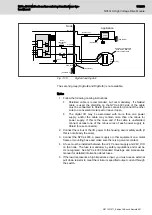
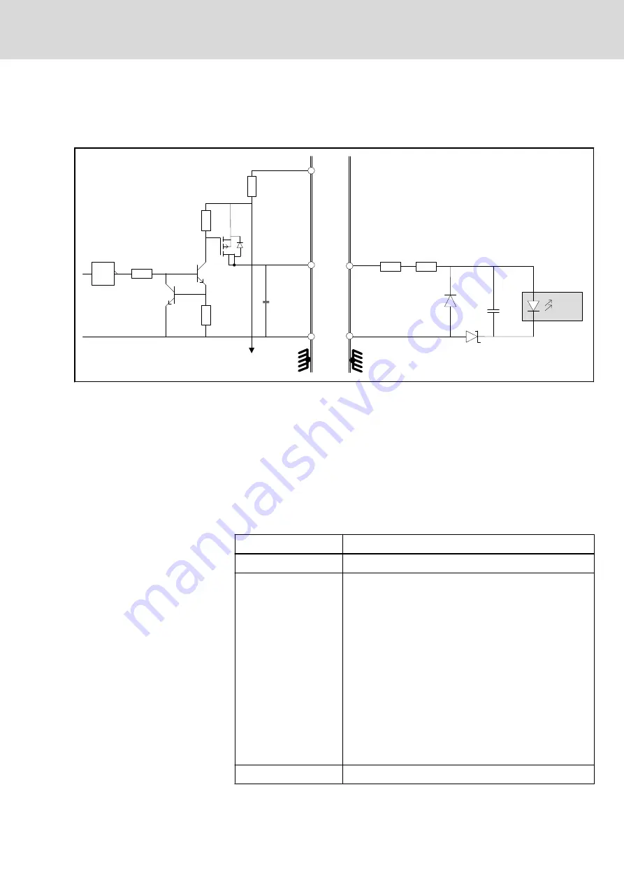
Fig. 11-14:
Output circuit for FastOut0, FastOut1, and input circuit for FastIn0,
FastIn1
For cabling and power supply connections of the fast digital inputs and fast
digital outputs the same rules apply as for normal digital inputs and outputs,
with one additional note. The cable with signal wire(s) of fast digital inputs
and/or fast digital outputs must also include the return current path for every
signal in the cable. For normal digital I/O this is recommended, but for fast
digital I/O this is mandatory.
11.12 5 Volt Digital Inputs
Characteristic
Description
Number of Hall inputs
3, Dig5VIn0a, Dig5VIn0b and Dig5VIn0c for axis0
Function
Hall Input (see note in
chapter 11.14.2 "Motor types" on
)
Quadrature counter inputs
Rexroth MSM encoder input
General purpose digital Input
Position latching
Change of state event (1 per MCU sample time)
Count transitions (1 per MCU sample time)
(Functionality available on the Dig5VIn pins of the encoder
headers of the system housing may be limited, because
these pins are also used to connect encoders. See the
encoder header pinout tables of the system housing in the
NYCe 4000 Standard Housings & Accessories manual).
Signal interface
RS485 or 5 V (half RS485 referenced to 2.05 V)
NYCe 4000 Multi-axis motion control system Hardware Sys‐
tem Manual
141/233
NY4140: High Voltage Drive Module
R911337671_Edition 18 Bosch Rexroth AG


