signal in the cable. For normal digital I/O this is recommended, but for fast
digital I/O this is mandatory.
9.10
TTL Digital Inputs
Characteristic
Description
Number of inputs
5, TTLIn0 … TTLIn4
Function
General purpose digital Input (for example for encoder
error signal). Other general purpose digital input
functionality, such as edge detection, counter
functionality, etc., is not supported.
In NYCe 4000 Software these inputs are referenced
with the following definitions:
●
Input TTLIn0 – referenced by identifier
NYCE_DIG5VIN0A
●
Input TTLIn1 – referenced by identifier
NYCE_DIG5VIN0B
●
Input TTLIn2 – referenced by identifier
NYCE_DIG5VIN0C
●
Input TTLIn3 – referenced by identifier
NYCE_DIG5VIN1A
●
Input TTLIn4 – referenced by identifier
NYCE_DIG5VIN1B
Signal interface
TTL logic
Galvanic insulated
No
Input thresholds
Input "low" voltage range: 0 … 0.8 V
Input "high" voltage range: 2.0 … 5.5 V
Input current
Typical 40 µA (input "low"), 1.4 mA (input "high")
Maximum input voltage
–5 … +10 V ±0.5 V
Interface type
TTL
Input frequency
1 MHz
Pull-up resistor for open
collector driver
No
Tab. 9-11:
Characteristics for TTL digital inputs
100 nF
1k
+3.3V
74LVT14
TTLIn
DGND
100k
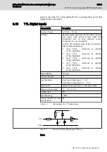
Fig. 9-11:
Input circuit of the digital inputs TTLIn0…4
Notes
NYCe 4000 Multi-axis motion control system Hardware Sys‐
tem Manual
95/233
NY4125: 5-axis low power PWM Drive Module
R911337671_Edition 18 Bosch Rexroth AG


