194
Kaleido-IP/Kaleido-X Cascade Step-by-Step Configuration
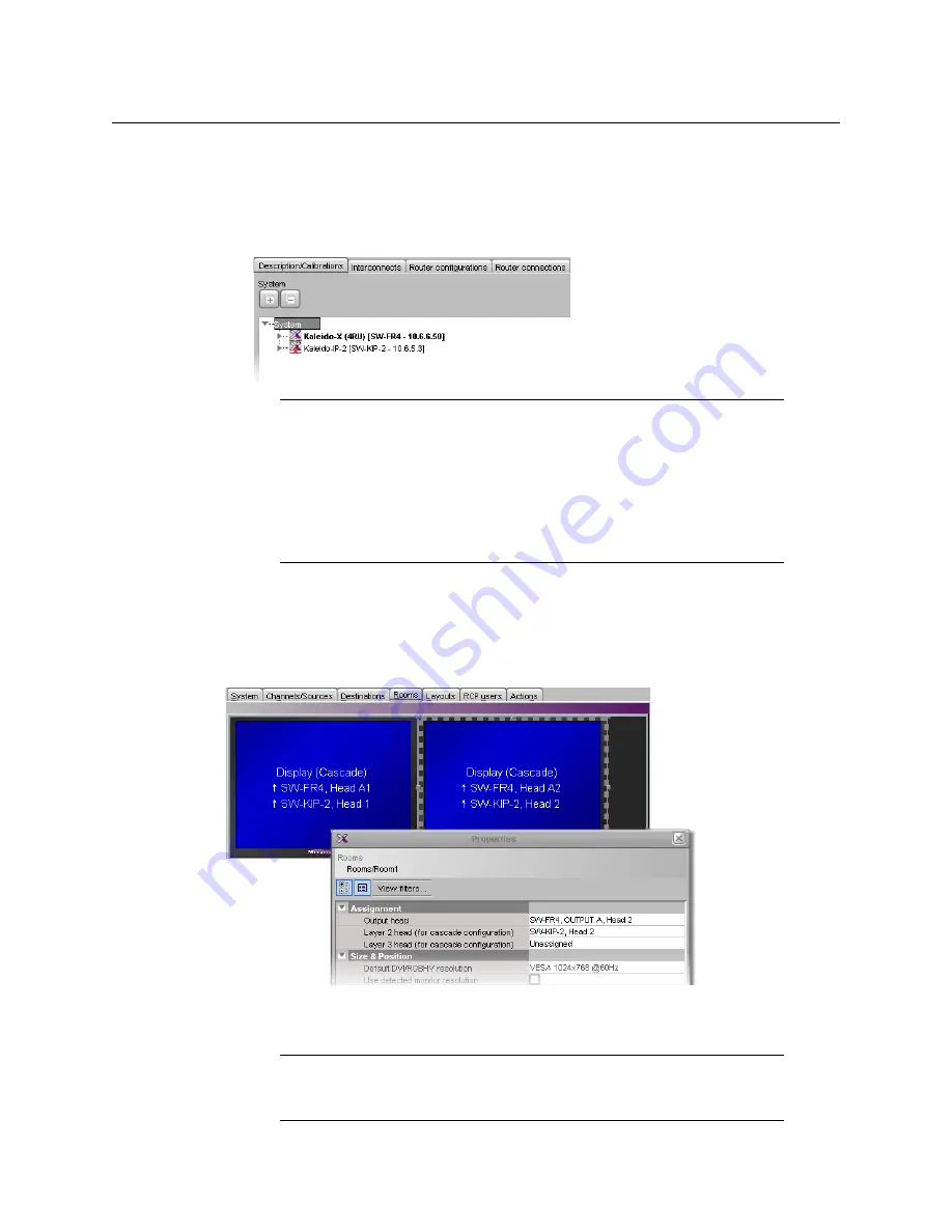
Configuring Cascade Rooms
3 If your PC and the multiviewer you wish to add are on the same subnet, then you can
select the multiviewer’s IP address from the list. Otherwise type the appropriate IP
address in the box.
4 Click
OK
.
The multiviewer is added to the System list.
Configuring Cascade Rooms
In a Kaleido-IP/Kaleido-X cascade room, each cascaded display is assigned heads from both
multiviewers, configured as layers, by setting the display’s
Output head
and
Layer 2 head
property to match the actual head order in your physical configuration.
To configure a cascade room
1 In XEdit, while connected to the Kaleido-X, open the room you wish to configure.
Notes
• The system type is automatically adjusted based on the actual target
system.
• Each member of a cluster has its own database where both common
information about the cluster and information local to the individual
cluster member are stored. Room and layout definitions are automatically
replicated to all cluster members, whereas the configuration for devices
connected to a specific system is only stored in this system’s database.
Note:
If the room does not exist yet, create it by adding the appropriate
number of displays, and then assign heads from the current multiviewer to
the displays in the usual fashion.
Summary of Contents for Grass Valley Kaleido-X
Page 22: ...22 Overview Functional Block Diagrams Simplified Signal Flow Diagram KX0 24Router...
Page 40: ...40 Installation Ventilation...
Page 100: ...100 IP Network Setup Network Considerations for a Multiviewer Cluster...
Page 123: ...123 Kaleido X 7RU Installation Service Manual 9 Click Finish A security warning appears...
Page 152: ...152 System Configuration Enabling Options...
Page 190: ...190 Maintenance Troubleshooting Disposal and Recycling Information...
Page 215: ...215 Kaleido X 7RU Installation Service Manual...


