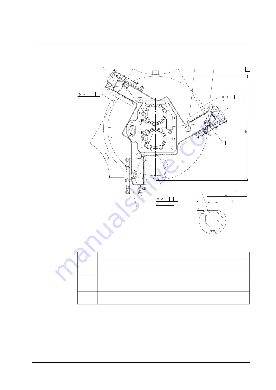
Hole configuration, base
This illustration shows the hole configuration used when securing the robot.
24.5°
3x 1
20°
60°
60°
65.5
°
740
CL J-K
1
2
A
B
3
0.1
F
G
0.08 J-K
0.1
F
G
0.08 J-K
0.1
F
G
0.08 J-K
G1
G2
G3
G
X
X
3x
30 H7
+
0.021
0
3x
5
0.1
3x M16
40
X-X
Z = 0
xx2000000018
Axis-1 gearbox
1
Axis-2 gearbox
2
Axis-3 gearbox
3
Attachment holes for lifting eyes
A
Robot mounting holes
B
Reference plane for each gearbox.
G1, G2,
G3
The three support points of the manipulator base box shall be mounted against
three flat surfaces with a flatness within the specification. Use shims if necessary.
See specification in
Requirements, foundation on page 38
Assembling and installing
The IRB 390 is delivered in sub-assemblies.
Continues on next page
Product manual - IRB 390
55
3HAC066566-001 Revision: B
© Copyright 2020 - 2021 ABB. All rights reserved.
3 Installation and commissioning
3.3.5 Orienting, assembling and securing the manipulator
Continued
Summary of Contents for IRB 390
Page 1: ...ROBOTICS Product manual IRB 390 ...
Page 8: ...This page is intentionally left blank ...
Page 14: ...This page is intentionally left blank ...
Page 36: ...This page is intentionally left blank ...
Page 44: ...This page is intentionally left blank ...
Page 118: ...This page is intentionally left blank ...
Page 330: ...This page is intentionally left blank ...
Page 344: ......
Page 345: ......


