


1-13
Click
Modify Port
to enter the page for modifying the VLANs to which a port belongs, as shown in
Figure 1-14
.
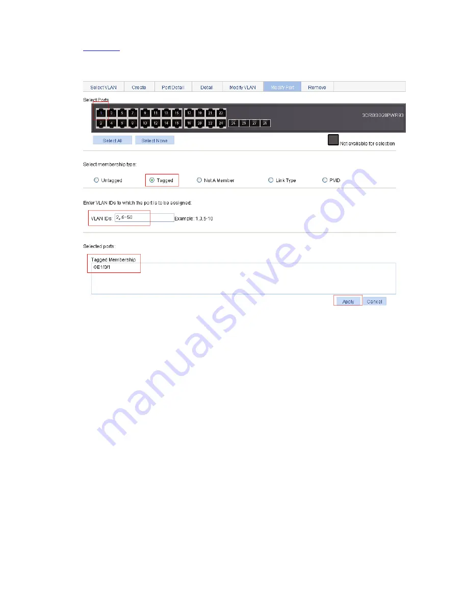
Figure 1-14
Assign GigabitEthernet 1/0/1 to VLAN 2, and VLAN 6 through VLAN 50 as a tagged
member
z
Select GigabitEthernet 1/0/1 on the chassis front device panel.
z
Select the
Tagged
radio button.
z
Type in VLAN IDs 2, 6-50.
z
Click
Apply
. A configuration progress dialog box appears.
z
After the configuration process is complete, click
Close
in the dialog box.
2) Configure Switch B
Configure Switch B as you configure Switch A.
Configuration Guidelines
When configuring VLAN, note that:
1) VLAN 1 is the default VLAN, which can be neither created nor removed manually.
2) Some VLANs are reserved for some special purposes. You can neither create nor remove them
manually.
3) Dynamic VLANs cannot be removed on the page for removing VLANs.
4) You cannot remove a VLAN that has referenced a QoS policy.
5) You cannot directly remove a VLAN configured as a remote probe VLAN. To remove the VLAN,
you must remove the remote probe VLAN configuration first.
Summary of Contents for 2928 - Baseline Plus Switch PWR
Page 92: ...1 9 Figure 1 7 Display the rate settings of ports ...
Page 105: ...1 4 Figure 1 3 Switch to the management level ...
Page 109: ...i Table of Contents 1 VCT 1 1 Overview 1 1 Testing Cable Status 1 1 ...
Page 114: ...1 2 Figure 1 2 Port traffic statistics ...
Page 279: ...1 28 Figure 1 26 The Port Setup tab ...
Page 331: ...i Table of Contents 1 Service Management 1 1 Overview 1 1 Configuring Service Management 1 2 ...


