8-40
INSTALLATION-PERIPHERALS
SECTION 400-096-208
SEPTEMBER 1992
transferred to (or programmed to ring)
the PSTU or PESU modem port to estab-
lish modem communication.
10 VOICE MAIL OPTIONS
10.00 System Hardware Requirements
10.01 STRATA DK systems can support a Toshiba
VP voice mail messaging system or a customer-
supplied voice mail system.
10.02 Voice mail systems connect to standard
telephone circuits (PSTU or PESU). The number of
circuits required by each device depends on the
customer’s voice mail requirements, such as the
number of voice mail users. The PCTU or PCTUS
must be equipped with a CRCU (-4 or -8) to support
voice mail.
10.10 Toshiba VP Voice Messaging System
10.11 STRATA DK systems are designed to sup-
port the full range of features offered by the Toshiba
VP. It provides various call routing, message
handling, and information management features,
including:
•
Auto Attendant
•
Call Forward to Voice Mailbox
•
Message Waiting Indication
•
Voice Mail Control from Digital and Electronic
Telephones
•
System Monitoring
•
Feature Integration
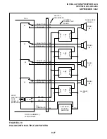
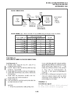
10.12 A block diagram of voice mail-to-PSTU or
-PESU connection is shown in Figure 8-26. See
section 400-096-206 for PSTU and PESU installa-
tion.
10.13 STRATA DK/Toshiba VP Programming
Considerations. Some features of STRATA DK
system programming were designed for Toshiba
VP systems, and do not necessarily apply to cus-
tomer-supplied voice mail messaging systems.
These programming features are as follows:
•
Answer (A) Tone. The STRATA DK stations
will send an answer tone to Toshiba VP when the
station answers a Toshiba VP call.
•
Disconnect (D) Tone. The STRATA DK sta-
tions will send a disconnect tone to Toshiba VP
when the station hangs up while connected to
Toshiba VP. (D Tone is also sent to release the
Toshiba VP/Auto Attendant port when an out-
side CO line caller hangs-up and the CO pro-
vides a Calling Party Control (CPC) or Auto
Release (AR) disconnect signal per Program
15-0.
NOTES:
1. D Tone will not operate in all areas, be-
cause some Central Offices fail to provide
the CPC or AR signal.
2. Both A and D Tones provide more efficient
Toshiba VP port use. Always enable these
options. Both options are enabled by ac-
cessing Program 31, and setting LEDs
15, 16 , and 17 ON.
3. The CPC or AR signal of some Central
Offices (COs) is not reliable and may
occur during a CO line voice connection,
causing the call to disconnect. If this oc-
curs, disable CPC /AR Hold and CPC/AR
Voice Mail calls on all CO lines with Pro-
grams 15-0 and 15-3.
•
B Tone Signals. Stations send a recall (B) tone
to Toshiba VP whenever they answer a transfer
(camp-on) recall from stations that did not an-
swer a Toshiba VP blind transfer. (The B tone
notifies Toshiba VP that the call is a recall and not
a new call, allowing Toshiba VP to respond with
the appropriate greeting.) For this feature to
operate, PSTU or PESU voice mail ports must
have LEDs 19 and 20 turned ON in Program 31.
10.14 See Paragraph 10.30 for general voice mail
programming information.
10.20 Customer-supplied Voice Mail Messag-
ing Systems
STRATA DK systems are designed to support a
wide range of customer-supplied voice mail mes-
saging systems. Depending on the voice mail sys-
tem used, some of the features available with
Toshiba VP (refer to Paragraph 10.10) may be
available with the customer-supplied system.
10.30 General Voice Mail (PSTU or PESU Port)
Содержание Strata DK 24
Страница 2: ......
Страница 10: ......
Страница 12: ...INSTALLATION SYSTEM DESCRIPTION SECTION 400 096 202 SEPTEMBER 1992 ...
Страница 42: ......
Страница 72: ......
Страница 102: ......
Страница 110: ......
Страница 144: ...INSTALLATION TELEPHONE SECTION 400 096 207 SEPTEMBER 1992 ...
Страница 164: ......
Страница 166: ...INSTALLATION PERIPHERALS SECTION 400 096 208 SEPTEMBER 1992 ...
Страница 170: ......
Страница 238: ...INSTALLATION WIRING DIAGRAMS SECTION 400 096 209 SEPTEMBER 1992 ...
Страница 300: ......
Страница 302: ...REMOTE ADMINISTRATION MAINTENANCE PROCEDURES SECTION 400 096 600 SEPTEMBER 1992 ...
Страница 372: ......


