background image

1-3

INSTALLATION-INTRODUCTION

SECTION 400-096-201

SEPTEMBER 1992

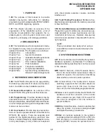
Telephone Interface Unit (PEKU) or a Standard
Telephone/Electronic Telephone Interface Unit
(PESU) equipped with an Off-hook Call An-
nounce subassembly (EOCU) to receive OCA,
and must have three-pair wiring and modular
cord.

IMDU: Remote Maintenance Modem Interface

Unit—A subassembly installed on an option
interface unit (PIOU or PIOUS) that allows the
system to be connected with a remote mainte-
nance/administration terminal.

KSU:  Key Service Unit—The system’s cabinet

with its common equipment.

LCD: Liquid Crystal Display—The display on digi-

tal and electronic telephones.

LED: Light Emitting Diode—Status indicators lo-

cated on printed circuit boards (PCBs), digital
telephones, and electronic telephones.

LSI:  Large Scale Integration—Related to circuit

design technology. STRATA DK printed circuit
boards (PCBs) use LSI circuit design.

MDF: Main Distribution Frame—The wiring frame

usually located in a phone closet.

MDFB: Door Phone Box—A peripheral two-way

speaker box option.

OCA: Off-hook Call Announce.

PBTC: A Toshiba-supplied cable used to connect

customer-supplied batteries to any DK PPSU
power supply for emergency reserve power.

PBX:  Private Branch Exchange—Industry-stan-

dard term which refers to a telephone switch,
usually on-premises, which serves an individual
company, and is connected to a public tele-
phone exchange through the Central Office
(CO).

PCB: Printed Circuit Board.

PCM: Pulse Code Modulation—A widely-used form

of digital telephone switching.

PCOU1:  CO Line Interface Unit—An optional

printed circuit board (PCB) that provides the
system with four CO lines.

PCOU2: Replaces PCOU1 and works exactly the

same way as PCOU1.

PCTU: Common Control Unit—The system’s con-

troller printed circuit board (PCB) that can sup-
port up to 14 universal slots, 96 station ports,
and 36 CO lines. There are four software versions
of the PCTU—PCTU1, PCTU2, PCTU3, and
PCTU4—each of which can be installed in any
STRATA DK system and supports a unique set
of features.

PCTUS:  Common Control Unit—A Release 2

controller printed circuit board (PCB) designed
for the DK24 that can support up to six universal
slots, 24 station ports and 16 CO lines.

PDIU-DI/PDIU-DI2 (Release 3 and Higher): Inte-

grated Data Interface Unit—Replaces the nor-
mal digital telephone base to enable the tele-
phone to be used for the transmission and
reception of data between a terminal/personal
computer connected to the telephone and de-
vices connected to other PDIU-DIs or to mo-
dems, printers, and computers connected to
PDIU-DSs. The PDIU-DI is also used to provide
personal computer access to outside dial-up
data services and/or bulletin boards via modem
pooling.

NOTE:
The PDIU-DI and the PDIU-DI2 are identical,
except that the PDIU-DI attaches to 1000-
series Digital Telephones, while the PDIU-
DI2 attaches to 2000-series Digital Tele-
phones.

PDIU-DS (Release 3 and Higher): Stand-alone

Data Interface Unit—Used for modem pooling,
printer sharing, and accessing host/mainframe
computer.

PDKU1 (Release 3 and Higher): Digital Tele-

phone Interface Unit—An optional printed cir-
cuit board (PCB) that provides the system with
eight digital telephone circuits. In addition to

Содержание Strata DK 24

Страница 1: ...s Division All rights reserved No part of this manual covered by the copyrights hereon may be reproduced in any form or by any means graphic electronic or mechanical including photocopying recording taping or information retrieval systems with the exception of the System Record forms without written permission of the publisher of this material SERIAL NO DK R4 D96 IM DKI M R4 4031006 ...

Страница 2: ......

Страница 3: ...INSTALLATION INTRODUCTION SECTION 400 096 201 SEPTEMBER 1992 TOSHIBA SYSTEM PRACTICES DIGITAL KEY TELEPHONE SYSTEMS RELEASE 1 2 3 and 4 INSTALLATION Chapter One INTRODUCTION ...

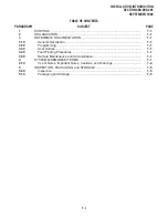
Страница 4: ...CUMENTATION 1 1 3 10 General Description 1 1 3 20 Programming 1 1 3 30 User Guides 1 1 3 40 Fault Finding Procedures 1 1 3 50 Remote Maintenance and Administration 1 1 4 SYSTEM MNEMONICS TERMS 1 1 4 10 Use of Notes Important Notes Cautions and Warnings 1 4 5 INSPECTION PACKAGING and STORAGE 1 5 5 00 Inspection 1 5 5 10 Packaging and Storage 1 5 1 i ...

Страница 5: ... to the STRATA DK system There are separate user guides for the digital telephone electronic tele phone standard telephone digital telephone Liq uid Crystal Display LCD electronic telephone LCD direct station selection console and data interface unit 3 40 Fault Finding Procedures Hardware trou bleshooting and diagnostic information presented in flowchart form 3 50 RemoteMaintenanceandAdministratio...

Страница 6: ... station with the touch of a flexible feature button DTMF Dual tone Multi frequency Push button dialing DVSU Release 3 and Higher A subassembly that equips a digital telephone with Off hook Call Announce capability EOCU Off hook Call Announce Subassembly An optional upgrade to the Electronic Tele phone Interface Unit PEKU that enables prop erly configured telephones see HVSU2 that are connected to...

Страница 7: ... digital telephone switching PCOU1 CO Line Interface Unit An optional printed circuit board PCB that provides the system with four CO lines PCOU2 Replaces PCOU1 and works exactly the same way as PCOU1 PCTU Common Control Unit The system s con troller printed circuit board PCB that can sup port up to 14 universal slots 96 station ports and36COlines Therearefoursoftwareversions of the PCTU PCTU1 PCT...

Страница 8: ...Interface Unit An optional printed circuit board PCB that provides support and or circuit interface for optional hardware peripher als and upgrades PIOUS The same as the PIOU with some excep tions most notably the PIOUS has one external paging interface zone while the PIOU has four NOTE Each system will support only one of the following PCBs PIOU PIOUS or PEPU Port A term used to identify a statio...

Страница 9: ...ntact the delivery carrier and your supplier immediately 5 03 Afterunpacking andbeforeinstalling check the system against the packing list and inspect all equipment for damage If equipment is missing or damaged contact your supplier immediately 5 04 Be sure to retain original packaging materi als for reuse when storing or transporting system hardware 5 10 Packaging and Storage CAUTION When handlin...

Страница 10: ......

Страница 11: ...INSTALLATION SYSTEM DESCRIPTION SECTION 400 096 202 SEPTEMBER 1992 TOSHIBA SYSTEM PRACTICES DIGITAL KEY TELEPHONE SYSTEMS RELEASE 1 2 3 and 4 INSTALLATION Chapter Two SYSTEM DESCRIPTION ...

Страница 12: ...INSTALLATION SYSTEM DESCRIPTION SECTION 400 096 202 SEPTEMBER 1992 ...

Страница 13: ... SYSTEM CONTROLS AND INDICATORS 2 13 8 PERIPHERAL EQUIPMENT 2 13 8 00 Digital Telephones 2 13 8 10 Electronic Telephones 2 19 8 20 Digital and Electronic Telephone Upgrade Options 2 19 8 30 Direct Station Selection Consoles 2 19 8 40 Toshiba supplied Peripherals 2 20 8 50 Customer supplied Peripherals 2 20 TABLE LIST TABLE TITLE PAGE 2 A TYPICAL RESERVE POWER FUNCTION ESTIMATES 2 6 2 B COMMON CONT...

Страница 14: ...L 2 5 2 8 POWER FAILURE TRANSFER UNIT DPFT 2 7 2 9 DPFT FUNCTIONAL BLOCK DIAGRAM 2 7 2 10 SYSTEM FUNCTIONAL BLOCK DIAGRAM 2 10 2 10 SYSTEM FUNCTIONAL BLOCK DIAGRAM continued 2 11 2 11 LOCATION OF DK24 CONTROLS AND INDICATORS 2 13 2 12 LOCATION OF DK56 CONTROLS AND INDICATORS 2 13 2 13 LOCATION OF DK96 CONTROLS AND INDICATORS 2 13 2 14 LOCATION OF PCB CONTROLS AND INDICATORS 2 14 ...

Страница 15: ...nd peripherals installed de pends on the user s requirements The primary differences between the STRATA DK systems are KSU sizes PCB capacities and power supplies 1 12 Hardware for all three system types is iden tical with the exception of the KSUs and power supplies Differences between models are identi fied as applicable 2 SYSTEM TECHNOLOGY 2 00 Custom Electronic Circuitry 2 01 STRATA DK system ...

Страница 16: ...le top mounted The KSU interior houses the printed circuit board PCB shelves and the power supply 3 02 External dimensions and approximate weights for the DK24 DK56 and DK96 models are listed below Weights are based on cabinets con taining a full complement of PCBs DK24 Height 10 6 in 269 mm Width 16 0 in 406 mm Depth 9 0 in 229 mm Weight 19 4 lbs 9 kg DK56 Height 15 0 in 381 mm Width 16 0 in 406 ...

Страница 17: ... D ON OFF POWER FG 24V1 24V2 SG FG PPSU 24 POWER 5V 5V 24V OUT CONNECTOR PCB SLOTS POWER SUPPLY D D PPSU56 24V 1 24V 2 24V 3 DC OUT POWER 5V 5V BATT _ SG FG LG FG ON OFF AC IN 1 6 FG PCTU PCTU S01 S02 S03 S04 S05 S06 S07 S08 POWER SUPPLY PCB SLOTS CONNECTOR FIGURE 2 3 DK56 KSU INTERIOR FIGURE 2 2 DK24 KSU INTERIOR ...

Страница 18: ... labeled S01 S08 The bottom shelf has seven available PCB slots labeled PCTU and S09 S14 Only the PCTU slot serves a dedicated function 3 32 PCB slots S01 S14 each incorporates a standard 40 pin female connector located in the same vertical position on the KSU s backplane This standardization enables any of the optional PCBs to be installed in any available slot The PCTU slot incorporates the same...

Страница 19: ...lure the systemautomaticallyswitchesovertobatterypower without any interruption to existing calls or other normal system functions The length of time re serve power operates depends on the system size number of batteries provided and the system load Typical reserve power duration estimates are provided in Table 2 A FIGURE 2 5 DK24 POWER SUPPLY FRONT PANEL _ BATT LG FG D D ON OFF POWER FG 24V1 24V2...

Страница 20: ...owerthesystemandthesystemWILL NOT operate 4 20 Battery Charger 4 21 To allow full normal system operation during a power failure the power supply has a built in current limiting battery charger that maintains cus tomer supplied batteries Electrical characteris tics of the battery charger include Nominal float voltage 2 275 volts cell Charge current 0 7 amps maximum Battery discharge cut off voltag...

Страница 21: ...nec tors are positioned in the same location on each board type 6 02 PCB external connections are made to the main distribution frame MDF using the following industry standard connectors 25 pair Amphenol Female Twenty five pair amphenol connectors connect digital tele CO LINE TEL LINE POWER FAILURE TRANSFER AMPHENOL CONNECTOR J1 AMPHENOL CONNECTOR J2 FIGURE 2 8 POWER FAILURE TRANSFER UNIT DPFT STA...

Страница 22: ...are feature set the PCTUS supports fewer universal slots stations and CO lines than the PCTU See Table 2 B for more PCTUS details CRCU Dual tone Multi frequency DTMF Re ceiver Subassembly The CRCU is an op tional DTMF receiver PCB which mounts on the PCTUorPCTUS piggyback style Ittranslates DTMF signals from Direct Inward System Ac cess DISA CO lines TIE lines standard tele phones or peripheral de...

Страница 23: ... 6 pair Modular Connector P Piggy back PCB T Terminal Connector X Option equipped TABLE 2 B COMMON CONTROL UNIT DATA PCTU Control Board PCTU1 PCTU2 PCTUS PCTU3 PCTU4 CPU Type 68000 16 bit 68000 16 bit 68000 16 bit 68000 16 bit 68000 16 bit Clock Speed 8 MHZ 8 MHZ 8 MHZ 8 MHZ 8 MHZ RAM Memory Capacity 256K 256K 128K 384K 384K ROM Memory Capacity 512K 512K 512K 768K 768K Feature Set Release 1 Releas...

Страница 24: ...IR MOD CORD MODULAR BLOCKS 3 PAIR MOD CORD 3 PAIR MOD CORD LINE 1 AND 2 32 CH CONF SW 4 3 2 1 CRCU PIOU PIOUS PEPU OPTION INTERFACE PCB 25 PAIR AMPHENOL PIOU PEPU OR SPRING TERMINAL STRIP PIOUS IMDU OPTIONAL BUILT IN MAINTENANCE MODEM TWISTED PAIR TOSHIBA PROGRAMMING TERMINAL OR MODEM CALL ACCOUNTING DEVICE OR PRINTER AMPLIFIED PAGE OUTPUT 3 WATTS MUSIC SOURCE EXTERNAL ZONE PAGE BACKGROUND MUSIC D...

Страница 25: ...IU MAINFRAME COMPUTER RS 232 CABLES RS 232 CABLES PRINTER SHARING PC DKT WITH DIU BASE DIGITAL TELEPHONE 1 PAIR MODULAR CORDS 1 OR 2 PAIR MODULAR CORDS RJ 11 MODULAR JACKS 117 VAC 15 AMP 50 60 HZ AC INPUT DKSU 24 56 96 5 VDC 24 VDC TO PCB PPSU MDFB DOOR PHONES AND LOCK CONTROLS BGM SOURCE TO STATIONS AND PAGE OUTPUT DIU DIU NOTES 1 2 3 TOSHIBA DDSS CONSOLE HDCB MDFB DOOR PHONES AND LOCK CONTROLS T...

Страница 26: ...g voltage Almost all nel and does not require a dedicated CO line or station port Data transmission speed can be set at 300 or 1200 bps full duplex PEPU External Page Interface Unit A reduced version of the PIOU the PEPU provides a circuit interface with the peripheral options listed in Table 2 C PESU Standard Electronic Telephone Inter face Unit This optional PCB which is avail able with Release ...

Страница 27: ...8 9 10 5 4 3 FIGURE 2 12 LOCATION OF DK56 CONTROLS AND INDICATORS in Figure 2 14 and described in Table 2 G 8 PERIPHERAL EQUIPMENT 8 00 Digital Telephones 8 01 STRATA DK systems support 2000 series Digital Telephones the DKT2010 H DKT2010 SD DKT2020 S and DKT2020 SD and 1000 series Digital Telephones the DKT1010 H and DKT1020 SD Digital telephones provide a num ber of standard useful features and ...

Страница 28: ...L MOH BGM SOURCE CONNECTOR PCTU 1 2 3 4 PCTUS PEPU VR1 3 WATT AMPLIFIER VOLUME CONTROL 50 PIN AMPHENOL CONNECTOR HEAT SINK PIOUS BAUD RATE SW2 LED CD4 600 OHM PAGE DOOR LOCK AMP MUTE NIGHT RELAY MOH CONTROL ALARM MODULAR JACK BAUD RATE LED VR1 3 WATT AMPLIFIER VOLUME CONTROL PIOU PIOU 50 PIN AMPHENOL CONNECTOR MODULAR JACK BAUD RATE SW2 LINE NUMBER 3 AND 4 LINE NUMBER 1 AND 2 4 3 2 1 LINE NUMBER L...

Страница 29: ...emain installed on SG FG terminal block for all system applications AC Power Cord 10 3 prong plug with power cord Cord for application of AC power from wall outlet FG Terminal not shown Combination slotted Phillips screw KSU frame ground terminal 24V Circuit Breaker Push to reset circuit breaker Circuit breaker for power supply 24VDC output to PCB slots S01 and S02 S03 Push to reset circuit breake...

Страница 30: ... male connector Interface connector for application of AC power from wall outlet FG Terminal not shown Combination slotted Phillips screw KSU frame ground terminal Interface connector for application of power supply 5VDC and 24VDC outputs to KSU s backplane DC OUT Connector 7 pin keyed male connector 24V Circuit Breaker Push to reset circuit breaker Circuit breaker for power supply 24VDC output to...

Страница 31: ...bination slotted Phillips screw KSU frame ground terminal Interface connector for application of power supply 5VDC and 24VDC outputs to KSU s backplane DC OUT Connector 7 pin keyed male connector 24V Circuit Breaker Push to reset circuit breaker Circuit breaker for power supply 24VDC output to PCB slots S01 and S02 Push to reset circuit breaker Circuit breaker for power supply 24VDC output to PCB ...

Страница 32: ...US1 Music on Hold Background Music Volume Control VR1 PCOU CO Line Indicators Four red LEDs Red LED Trim potentiometer Flashes to indicate operation 1 4 second on 1 4 second off Adjusts volume for music on hold background music feature Lights to indicate the applicable CO line is in operation NOTE CO line indicators will not light unless PCOU is connected to a CO line PEMU E M TIE Line Indicators ...

Страница 33: ...e PDIU DI2 can be mounted in a 2000 series Digital Telephone while the PDIU DI can be mounted in a 1000 series Digital Telephone NOTES 1 The PDIU DI will function with all slots except slots 11 14 in DK96 2 PDKU1A Circuits 1 7 only can support PDIU DIs PDIU DI2s while all PDKU2A circuits 1 8 can support PDIU DIs PDIU DI2s Off hook Call Announce Upgrade DVSU HVSU2 ADVSUsubassemblycanbeinstalled in ...

Страница 34: ...electronic door lock with the touch of a button on a digital or electronic telephone Each door lock must connect with ei ther a door phone lock control unit DDCB or HDCB or a PIOU PIOUS or PESU PCB NOTES 1 TheDDCBisonlyavailablewithRelease4 2 Each door lock that interfaces with a DDCB or HDCB reduces the door phone capacity of 12 by one 8 45 TOSHIBA VP Systems TOSHIBA VP the VP 100 VP 200 and VP 3...

Страница 35: ...INSTALLATION SITE REQUIREMENTS SECTION 400 096 203 SEPTEMBER 1992 TOSHIBA SYSTEM PRACTICES DIGITAL KEY TELEPHONE SYSTEMS RELEASE 1 2 3 and 4 INSTALLATION Chapter Three SITE REQUIREMENTS ...

Страница 36: ...Requirements and Characteristics 3 1 4 CABLE LENGTHS NETWORK REQUIREMENTS 3 3 5 GROUNDING REQUIREMENTS 3 3 5 10 Third Wire Ground Test 3 3 5 20 Frame Ground Test 3 5 TABLE LIST TABLE TITLE PAGE 3 A SUMMARY OF ELECTRICAL ENVIRONMENTAL CHARACTERISTICS 3 2 3 B LOOP REQUIREMENTS 3 3 3 C NETWORK REQUIREMENTS 3 4 FIGURE LIST FIGURE TITLE PAGE 3 1 DK24 56 MINIMUM CLEARANCE REQUIREMENTS 3 1 3 2 DK96 MINIM...

Страница 37: ...ted on a wall or tabletop Figure 3 1 DK24 56 and Figure 3 2 DK96 show the mini mum clearance requirements for both mounting options 3 02 The following conditions must be considered when selecting a location for the KSU The location MUST BE Dry and clean Well ventilated Well illuminated Easily accessible The location MUST NOT BE Subject to extreme heat or cold Subject to corrosive fumes dust or oth...

Страница 38: ... 70 C Charger current limiting Nominal Float Voltage 2 275 volts cell Charge Current 0 7 amps maximum Battery Discharge Cut off Voltage 20 5 0 5V 24 VDC 26 3 27 8 5 VDC 4 5 5 5 5 VDC 4 5 5 5 PSTU2 PESU circuits 1 2 Ring Voltage Ringing Capability Low position 130 20V peak to peak no load High position 190 25V peak to peak no load Two ringers maximum per circuit high or low position PDKU 5 205 BTUs...

Страница 39: ...proper operation Failure to provide ground may lead to confusing trouble symptoms and in ex treme cases system failure The AC power cord already contains a conductor for the third wire ground provided by the commercial power outlet butconnectaconductorbetweentheframeground terminal on the key service unit KSU and a cold NOTES 1 Some distance limitations apply See Table 9 D 2 Requires 3 pair to rec...

Страница 40: ...1 Obtain a suitable voltmeter and set it for a possible reading of up to 250VAC 2 Connect the meter probes between the two main AC voltage terminals white and black wires on the wall outlet The reading ob tained should be between 100 120VAC 3 Move one of the meter probes to the third terminal green wire ground Either the same reading or a reading of zero volts should be obtained 4 If the reading i...

Страница 41: ...If the above tests show the outlet is not properly grounded the condition should be corrected per Article 250 of the National Electrical Code by a qualified electrician before the system is connected 5 20 Frame Ground Test 5 21 Use the following procedure to test the frame ground conductor for continuity WARNING Hazardous voltages that may cause death or injury may be exposed during the fol lowing...

Страница 42: ......

Страница 43: ...INSTALLATION CONFIGURATION SECTION 400 096 204 SEPTEMBER 1992 TOSHIBA SYSTEM PRACTICES DIGITAL KEY TELEPHONE SYSTEMS RELEASE 1 2 3 and 4 INSTALLATION Chapter Four SYSTEM CONFIGURATION ...

Страница 44: ...ATION GUIDE WORKSHEET 3 4 17 CONFIGURATION GUIDE WORKSHEET 4 4 18 CONFIGURATION GUIDE WORKSHEET 5 4 19 CONFIGURATION GUIDE WORKSHEET 6 4 20 CONFIGURATION GUIDE WORKSHEET 7 4 22 4 SYSTEM HARDWARE CONFIGURATION 4 23 4 00 General 4 23 4 10 System Hardware Assignment Record 4 23 4 20 Door Phone Hardware Configuration Notes 4 25 4 30 DSS Console Hardware Configuration Notes 4 26 4 40 Data Interface Uni...

Страница 45: ...their ability to meet a broad range of customer configu ration requirements A modular building block ap proach allows the incremental addition of various parts to meet growing and changing system needs and applications 1 02 The main unit of each STRATA DK system is the key service unit KSU which contains universal slots that can support any of the various station CO line and peripheral printed cir...

Страница 46: ...if ferent series telephones and or if a PEMU PCB is installed use Worksheet 7 in the Configuration Guide to verify that the power supplied is greater than the power used 1 20 Common Control PCBs 1 21 DK systems must be configured with one of the following five common control PCBs PCTU1 PCTU2 PCTU3 PCTU4 or PCTUS PCTU1 2 3 and 4 have the same configuration capacity and canbeusedinallthreesystemmode...

Страница 47: ...or combination Door Phones Simultaneous Multi party Conference CRCU 4 or 8 Option DK24 56 96 PCTU1 Release 1 PCTU2 Release 2 PCTU3 Release 3 PCTU4 Release 4 6 max with DK24 8 max with DK56 14 max with DK96 12 max 5 max R2 R3 and R4 1 max R1 8 max 1 max CO Line Capacity squared systems Door Lock Controls PCTU MOH BGM Connection 24 max 32 max with DK24 56 max with DK56 96 max with DK96 4 max with DK...

Страница 48: ...s One PESU PCB One CRCU subassembly Each of these PCBs except for the CRCU requires one universal slot Therefore a total of 10 slots are required This is beyond the capacity of DK24 and DK56 six and eight slots respectively but well within the capac ity of DK96 The CRCU which mounts on the PCTU is required for the DTMF standard telephones 2 OPTIONS AND PERIPHERALS 2 00 Option Printed Circuit Board...

Страница 49: ...oor Phone Box 8 Digital Telephone Ports Digital without PDIU DI with PDIU DI PDKU1 requires PCTU3 or PCTU4 3 24 N A N A 4 32 32 21 2 8 64 64 53 2 12 96 96 80 2 NOTES 1 The appropriate capacities apply to digital and 6500 series electronic telephones only If other Toshiba electronic telephones 2000 3000 6000 are used refer to Worksheet 7 2 The number of digital telephones with PDIU DIs is limited b...

Страница 50: ...SCII Terminal or External Modem RS 232 6 wire modular connector X X X X X X X X X X X X X X X X X X X X NOTE X indicates the option is provided digital or electronic telephone or one DSS console to each of four digital or electronic telephones or anyintermediatecombination Furthermore DDSS consolescanbeassignedtoelectronictelephones althoughthetelephonesandtheconsolesinterface with different types...

Страница 51: ... DI and PDIU DI2 The PDIU DI 2 can replace the normal base of the digital telephone to provide the telephone with Data Calling capability Each sys tem can support a maximum number of PDIU DI 2 s as shown in Table 4 B The PDIU DI 2 which is attached to the digital telephone shares the same digital circuit on the PDKU NOTE The PDIU DI and the PDIU DI2 are identical except that the PDIU DI attaches t...

Страница 52: ...s 04 12 20 and 28 and the HDCB which can be supported by the PCTUS as well as all versions of the PCTU connects to electronic circuits associated with four ports For system configuration each DDCB and HDCB must be considered equivalent to a telephone as far as consuming station capacity Table 4 E provides more details regarding DDCB and HDCB configu ration 2 40 E M TIE Lines 2 41 Each PEMU PCB pro...

Страница 53: ...en of the 37 electronic telephones and three zone paging The business also wishes to use the Direct Inward System Access DISA feature The four door phones can be supported by two HDCBs since each HDCB has a maxi mum of three door phone interfaces Each HDCB requires one electronic telephone cir cuit Both HDSS consoles require two elec tronic telephone circuits Therefore includ ing the 37 electronic...

Страница 54: ...dant station Intercom numberingcanbecompletelyflexiblyassigned but is best left to the consecutive standard numbering of 200 295 with PCTU 1 2 3 and 4 and 200 223 with PCTUS User guides are written using this standard plan and LCD digital and electronic tele phone busy fields will be meaningful only if the last two digits of the intercom number are consecutive starting with 00 NOTES 1 Each PEMU us...

Страница 55: ...amplifier with HESB Used for transmitting and receiving data between terminals personal computers and devices connected to other PDIUs The PDIU DI is also used to provide personal computer access to outside dial up data services and or bulletin boards via modem pooling For making switched data connections for modem pooling printer sharing and host mainframe computer accessing PIOU PIOUS PEPU for p...

Страница 56: ...l Announce path for all electronic telephone circuits of main PCB Provides DTMF receiver for DISA standard telephone VM circuits and TIE lines Remote maintenance interface with built in modem Interface for headset and Loud Ringing Bell2 Interface for digital telephone to receive Off hook Call Announce Interface for electronic telephone to receive Off hook Call Announce NOTES 1 An EOCU OCA will not...

Страница 57: ...telephones required refer to PEKU and PESU in Table 4 C NOTE If upgrading an existing STRATA DK system using 2000 3000 6000 6005 series electronic telephones and or if the system requires TIE lines PEMU refer to the System Power Check Worksheet 7 B4 Separate BGM source connected to electronic telephone circuit required 1 maximum B5 External amplifiers for two CO line amplified conference required ...

Страница 58: ...C E Number of E M TIE lines required refer to PEMU in Table 4 C D CO lines E TIE lines F Optional Interface PCB G Does the customer require other optional features yes or no for each battery backup power failure transfer unit DTMF signals from standard telephone ports off hook call announce headsets built in remote maintenance loud ringing bell talkback amplifier external page amplifier speaker do...

Страница 59: ... see Worksheet 1 A1 DDCBs see Worksheet 1 A2 PDIU DSs see Worksheet 1 A3 Digital telephones with or without PDIU DIs see Worksheet 1 A4 A1 A2 A3 A4 X X X X 1 1 1 1 2 Determine the minimum PDKU PCBs required using Chart 2A Total PDKU Ports CHART 2A MINIMUM PDKU PCB REQUIREMENTS Total Ports Chart 1A Minimum PDKU PCBs Am 01 08 09 16 17 24 25 32 33 40 41 48 49 56 57 64 65 72 73 80 81 88 89 96 1 2 3 4 ...

Страница 60: ... B2 B3 B4 B5 X X X X X 2 1 1 1 2 2 Determine the minimum PEKU PCBs required using Chart 2 Total PEKU Ports CHART 2 MINIMUM PEKU PCB REQUIREMENTS Total Ports Chart 1 Minimum PEKU PCBs Bm 01 08 09 16 17 24 25 32 33 40 41 48 49 56 57 64 65 72 73 80 81 88 89 96 1 2 3 4 5 6 7 8 9 10 11 12 3 Determine the actual PEKU PCBs required using Charts 1 and 2 as follows Actual PEKUs BT Bm or B1 or B2 whichever ...

Страница 61: ... C2 X X 1 1 2 Determine the actual PSTU PCB requirements using Chart 4 CHART 4 ACTUAL PSTU PCB REQUIREMENTS Total Ports Chart 3 PSTU PCBs 01 08 09 16 17 24 25 32 33 40 41 48 49 56 57 64 65 72 73 80 81 88 89 96 1 2 3 4 5 6 7 8 9 10 11 12 3 PESU In a configuration requiring less than two PSTU station ports a PESU PCB can be used in place of a PSTU PCB Normally only one PESU is installed in a system ...

Страница 62: ... 4 5 6 7 8 9 CO lines 2 Determine the number of PCOU PCBs using Chart 5 E PEMU PCBs four TIE lines Actual PEMU PCBs ET 1 Enter the number of TIE lines required from paragraph E of Worksheet 1 CHART 6 ACTUAL PEMU PCB REQUIREMENTS TIE Lines PEMU PCBs 01 04 05 08 09 12 1 2 3 TIE lines 2 Determine the number of PEMU PCBs using Chart 6 F PIOU PIOUS PEPU PCBs Enter type of optional interface from Paragr...

Страница 63: ...six or less d Total PEMU PCBs one or less e Combined DDSS and HDSS consoles four or less f DDCB HDCB controllers four or less g If using 2000 3000 6000 6005 series electronic telephones PDIU DIs and or a PEMU use Power Check Worksheet 7 DK24 with PCTU1 2 3 or 4 4 If total is eight or less use DK56 and PCTU 1 2 3 or 4 with the following considerations a PDKU PEKU PSTU PESU PCBs combined eight or le...

Страница 64: ... required for each digital telephone that must receive OCA Actual DVSU J HVSU2 refer to Table 4 F Electronic telephones equipped with an HVSU2 can receive OCA calls Actual HVSU2s K HVSU HVSI refer to Table 4 F Electronic telephones equipped with the HVSI and HVSU subassemblies can receive OCA calls Actual HVSUs HVSIs L IMDU PCB refer to Table 4 F One IMDU PCB must be installed on the PIOU or PIOUS...

Страница 65: ...back amplifier page speaker may be used in place of HESB Actual HESBs P PBTC 3M Cable One PBTC 3M cable is required for each system that requires battery backup batteries are customer supplied PBTC 3M Q PPTC Adaptor Modular to RS 232 A PPTC is required one each to connect a printer or call accounting device to the PIOU or PIOUS SMDR port or to connect a modem or ASCII terminal to the PIOU or PIOUS...

Страница 66: ...ies electronic telephone 6005 series electronic telephone 6500 series electronic telephone DDSS HDSS console PDIU DI PDIU DS Standard telephone PEMU PCB X X X X X X X X X X X 1 0 2 0 2 5 2 0 2 0 1 0 0 8 0 5 0 8 1 0 8 0 Total Power Used Total Power Used Power Supplied All series Power Supply PPSU 24 PPSU 56 PPSU 96 Power Supplied 32 80 144 Power Criteria Power Supplied Must be greater than zero Con...

Страница 67: ... PCTU or PCTUS will be equipped with a CRCU record the CRCU 4 or CRCU 8 under the PCTU slot A special PCB code is required for the PCBs that support the CRCU option EOCU If a PEKU or PESU is required to support Off hook Call Announce record EOCU under 3 00 To use a methodical step by step procedure to configureasystem aconfigurationguideconsistingof seven worksheets is provided in this chapter 4 S...

Страница 68: ... code must be entered for PDKU PCBs that support digital telephones with PDIU DI 2 s PDIU DSs will not function in Slots 11 14 on DK96 and Slots 05 and 06 on DK24 with PCTUS Also PDKU1A Circuit 8 will not support a PDIU DI 2 4 15 PCB Code Assignments Each PCB type has an identification code that must be entered in Program 03 If the PCB supports an option a special PCB code may have to be entered t...

Страница 69: ... the PEMU is installed in a PCTU 1 2 3 or 4 controlled DK24 24 stations will be available because of power supply capacity 4 17 CO Line Number Assignments Line cir cuits are provided by the PCOU and PEMU PCBs Each PCOU provides four line circuits for CO loop start line connections and each PEMU has four line circuits that support TIE lines Each of the PCBs must have line numbers assigned Record CO...

Страница 70: ...ociated electronic telephone on Circuit 1 of the same PEKU which in turn is referred to as a DSS attendant telephone An HDSS console though can be reassigned in system program ming to be associated with a digital telephone One PDKU PCB is required for each DDSS console and one PEKU is needed for each HDSS console The DDSS console connects to Circuit 8 of a PDKU and the HDSS console connects to Cir...

Страница 71: ... 61 62 64 21 22 23 24 31 11 13 25 41 21 00 DSS1 ATT1 DDCB 04 DK 96 Bottom Shelf SLOT NO PCB CODE PCB TYPE OPTIONS STA PORT NO s CO TIE LINE NO s 00 PCTU 92 09 PCOU 11 11 56 63 25 14 PIOU 41 10 09 12 PCOU 11 13 00 12 05 08 PESU 13 CRCU4 IMDU PEMU 64 67 13 16 PORTS TYPE NONE NONE NONE 8 STA 8 STA 8 STA 8 STA 8 STA 8 STA 8 STA 8 STA 4 CO 4 CO 4 STA 8 STA 8 STA NONE NONE PCTU PCTU CRCU4 PCTU CRCU8 PDK...

Страница 72: ......

Страница 73: ...INSTALLATION KSU SECTION 400 096 205 SEPTEMBER 1992 TOSHIBA SYSTEM PRACTICES DIGITAL KEY TELEPHONE SYSTEMS RELEASE 1 2 3 and 4 INSTALLATION Chapter Five KSU INSTALLATION ...

Страница 74: ...WER SUPPLY REMOVAL AND REPLACEMENT 5 3 4 10 Power Supply Removal 5 4 4 20 Power Supply Replacement 5 4 5 CIRCUIT BREAKER DISTRIBUTION 5 5 6 VOLTAGE TROUBLESHOOTING 5 5 FIGURE LIST FIGURE TITLE PAGE 5 1 WALL MOUNTING BRACKET INSTALLATION 5 1 5 2 KSU WALL MOUNTING 5 2 5 3 PPSU24 FRONT PANEL AND DC OUT TEST POINTS 5 3 5 4 PPSU56 FRONT PANEL AND DC OUT TEST POINTS 5 4 5 5 PPSU96 FRONT PANEL AND DC OUT...

Страница 75: ...their ability to meet a broad range of customer configu ration requirements A modular building block ap proach allows the incremental addition of various parts to meet growing and changing system needs and applications 1 02 The main unit of each STRATA DK system is the key service unit KSU which contains universal slots that can support any of the various station CO line and peripheral printed cir...

Страница 76: ...if ferent series telephones and or if a PEMU PCB is installed use Worksheet 7 in the Configuration Guide to verify that the power supplied is greater than the power used 1 20 Common Control PCBs 1 21 DK systems must be configured with one of the following five common control PCBs PCTU1 PCTU2 PCTU3 PCTU4 or PCTUS PCTU1 2 3 and 4 have the same configuration capacity and canbeusedinallthreesystemmode...

Страница 77: ...or combination Door Phones Simultaneous Multi party Conference CRCU 4 or 8 Option DK24 56 96 PCTU1 Release 1 PCTU2 Release 2 PCTU3 Release 3 PCTU4 Release 4 6 max with DK24 8 max with DK56 14 max with DK96 12 max 5 max R2 R3 and R4 1 max R1 8 max 1 max CO Line Capacity squared systems Door Lock Controls PCTU MOH BGM Connection 24 max 32 max with DK24 56 max with DK56 96 max with DK96 4 max with DK...

Страница 78: ...s One PESU PCB One CRCU subassembly Each of these PCBs except for the CRCU requires one universal slot Therefore a total of 10 slots are required This is beyond the capacity of DK24 and DK56 six and eight slots respectively but well within the capac ity of DK96 The CRCU which mounts on the PCTU is required for the DTMF standard telephones 2 OPTIONS AND PERIPHERALS 2 00 Option Printed Circuit Board...

Страница 79: ...oor Phone Box 8 Digital Telephone Ports Digital without PDIU DI with PDIU DI PDKU1 requires PCTU3 or PCTU4 3 24 N A N A 4 32 32 21 2 8 64 64 53 2 12 96 96 80 2 NOTES 1 The appropriate capacities apply to digital and 6500 series electronic telephones only If other Toshiba electronic telephones 2000 3000 6000 are used refer to Worksheet 7 2 The number of digital telephones with PDIU DIs is limited b...

Страница 80: ...SCII Terminal or External Modem RS 232 6 wire modular connector X X X X X X X X X X X X X X X X X X X X NOTE X indicates the option is provided digital or electronic telephone or one DSS console to each of four digital or electronic telephones or anyintermediatecombination Furthermore DDSS consolescanbeassignedtoelectronictelephones althoughthetelephonesandtheconsolesinterface with different types...

Страница 81: ... DI and PDIU DI2 The PDIU DI 2 can replace the normal base of the digital telephone to provide the telephone with Data Calling capability Each sys tem can support a maximum number of PDIU DI 2 s as shown in Table 4 B The PDIU DI 2 which is attached to the digital telephone shares the same digital circuit on the PDKU NOTE The PDIU DI and the PDIU DI2 are identical except that the PDIU DI attaches t...

Страница 82: ...s 04 12 20 and 28 and the HDCB which can be supported by the PCTUS as well as all versions of the PCTU connects to electronic circuits associated with four ports For system configuration each DDCB and HDCB must be considered equivalent to a telephone as far as consuming station capacity Table 4 E provides more details regarding DDCB and HDCB configu ration 2 40 E M TIE Lines 2 41 Each PEMU PCB pro...

Страница 83: ...en of the 37 electronic telephones and three zone paging The business also wishes to use the Direct Inward System Access DISA feature The four door phones can be supported by two HDCBs since each HDCB has a maxi mum of three door phone interfaces Each HDCB requires one electronic telephone cir cuit Both HDSS consoles require two elec tronic telephone circuits Therefore includ ing the 37 electronic...

Страница 84: ...dant station Intercom numberingcanbecompletelyflexiblyassigned but is best left to the consecutive standard numbering of 200 295 with PCTU 1 2 3 and 4 and 200 223 with PCTUS User guides are written using this standard plan and LCD digital and electronic tele phone busy fields will be meaningful only if the last two digits of the intercom number are consecutive starting with 00 NOTES 1 Each PEMU us...

Страница 85: ...amplifier with HESB Used for transmitting and receiving data between terminals personal computers and devices connected to other PDIUs The PDIU DI is also used to provide personal computer access to outside dial up data services and or bulletin boards via modem pooling For making switched data connections for modem pooling printer sharing and host mainframe computer accessing PIOU PIOUS PEPU for p...

Страница 86: ...l Announce path for all electronic telephone circuits of main PCB Provides DTMF receiver for DISA standard telephone VM circuits and TIE lines Remote maintenance interface with built in modem Interface for headset and Loud Ringing Bell2 Interface for digital telephone to receive Off hook Call Announce Interface for electronic telephone to receive Off hook Call Announce NOTES 1 An EOCU OCA will not...

Страница 87: ...telephones required refer to PEKU and PESU in Table 4 C NOTE If upgrading an existing STRATA DK system using 2000 3000 6000 6005 series electronic telephones and or if the system requires TIE lines PEMU refer to the System Power Check Worksheet 7 B4 Separate BGM source connected to electronic telephone circuit required 1 maximum B5 External amplifiers for two CO line amplified conference required ...

Страница 88: ...C E Number of E M TIE lines required refer to PEMU in Table 4 C D CO lines E TIE lines F Optional Interface PCB G Does the customer require other optional features yes or no for each battery backup power failure transfer unit DTMF signals from standard telephone ports off hook call announce headsets built in remote maintenance loud ringing bell talkback amplifier external page amplifier speaker do...

Страница 89: ... see Worksheet 1 A1 DDCBs see Worksheet 1 A2 PDIU DSs see Worksheet 1 A3 Digital telephones with or without PDIU DIs see Worksheet 1 A4 A1 A2 A3 A4 X X X X 1 1 1 1 2 Determine the minimum PDKU PCBs required using Chart 2A Total PDKU Ports CHART 2A MINIMUM PDKU PCB REQUIREMENTS Total Ports Chart 1A Minimum PDKU PCBs Am 01 08 09 16 17 24 25 32 33 40 41 48 49 56 57 64 65 72 73 80 81 88 89 96 1 2 3 4 ...

Страница 90: ... B2 B3 B4 B5 X X X X X 2 1 1 1 2 2 Determine the minimum PEKU PCBs required using Chart 2 Total PEKU Ports CHART 2 MINIMUM PEKU PCB REQUIREMENTS Total Ports Chart 1 Minimum PEKU PCBs Bm 01 08 09 16 17 24 25 32 33 40 41 48 49 56 57 64 65 72 73 80 81 88 89 96 1 2 3 4 5 6 7 8 9 10 11 12 3 Determine the actual PEKU PCBs required using Charts 1 and 2 as follows Actual PEKUs BT Bm or B1 or B2 whichever ...

Страница 91: ... C2 X X 1 1 2 Determine the actual PSTU PCB requirements using Chart 4 CHART 4 ACTUAL PSTU PCB REQUIREMENTS Total Ports Chart 3 PSTU PCBs 01 08 09 16 17 24 25 32 33 40 41 48 49 56 57 64 65 72 73 80 81 88 89 96 1 2 3 4 5 6 7 8 9 10 11 12 3 PESU In a configuration requiring less than two PSTU station ports a PESU PCB can be used in place of a PSTU PCB Normally only one PESU is installed in a system ...

Страница 92: ... 4 5 6 7 8 9 CO lines 2 Determine the number of PCOU PCBs using Chart 5 E PEMU PCBs four TIE lines Actual PEMU PCBs ET 1 Enter the number of TIE lines required from paragraph E of Worksheet 1 CHART 6 ACTUAL PEMU PCB REQUIREMENTS TIE Lines PEMU PCBs 01 04 05 08 09 12 1 2 3 TIE lines 2 Determine the number of PEMU PCBs using Chart 6 F PIOU PIOUS PEPU PCBs Enter type of optional interface from Paragr...

Страница 93: ...six or less d Total PEMU PCBs one or less e Combined DDSS and HDSS consoles four or less f DDCB HDCB controllers four or less g If using 2000 3000 6000 6005 series electronic telephones PDIU DIs and or a PEMU use Power Check Worksheet 7 DK24 with PCTU1 2 3 or 4 4 If total is eight or less use DK56 and PCTU 1 2 3 or 4 with the following considerations a PDKU PEKU PSTU PESU PCBs combined eight or le...

Страница 94: ... required for each digital telephone that must receive OCA Actual DVSU J HVSU2 refer to Table 4 F Electronic telephones equipped with an HVSU2 can receive OCA calls Actual HVSU2s K HVSU HVSI refer to Table 4 F Electronic telephones equipped with the HVSI and HVSU subassemblies can receive OCA calls Actual HVSUs HVSIs L IMDU PCB refer to Table 4 F One IMDU PCB must be installed on the PIOU or PIOUS...

Страница 95: ...back amplifier page speaker may be used in place of HESB Actual HESBs P PBTC 3M Cable One PBTC 3M cable is required for each system that requires battery backup batteries are customer supplied PBTC 3M Q PPTC Adaptor Modular to RS 232 A PPTC is required one each to connect a printer or call accounting device to the PIOU or PIOUS SMDR port or to connect a modem or ASCII terminal to the PIOU or PIOUS...

Страница 96: ...ies electronic telephone 6005 series electronic telephone 6500 series electronic telephone DDSS HDSS console PDIU DI PDIU DS Standard telephone PEMU PCB X X X X X X X X X X X 1 0 2 0 2 5 2 0 2 0 1 0 0 8 0 5 0 8 1 0 8 0 Total Power Used Total Power Used Power Supplied All series Power Supply PPSU 24 PPSU 56 PPSU 96 Power Supplied 32 80 144 Power Criteria Power Supplied Must be greater than zero Con...

Страница 97: ... PCTU or PCTUS will be equipped with a CRCU record the CRCU 4 or CRCU 8 under the PCTU slot A special PCB code is required for the PCBs that support the CRCU option EOCU If a PEKU or PESU is required to support Off hook Call Announce record EOCU under 3 00 To use a methodical step by step procedure to configureasystem aconfigurationguideconsistingof seven worksheets is provided in this chapter 4 S...

Страница 98: ... code must be entered for PDKU PCBs that support digital telephones with PDIU DI 2 s PDIU DSs will not function in Slots 11 14 on DK96 and Slots 05 and 06 on DK24 with PCTUS Also PDKU1A Circuit 8 will not support a PDIU DI 2 4 15 PCB Code Assignments Each PCB type has an identification code that must be entered in Program 03 If the PCB supports an option a special PCB code may have to be entered t...

Страница 99: ... the PEMU is installed in a PCTU 1 2 3 or 4 controlled DK24 24 stations will be available because of power supply capacity 4 17 CO Line Number Assignments Line cir cuits are provided by the PCOU and PEMU PCBs Each PCOU provides four line circuits for CO loop start line connections and each PEMU has four line circuits that support TIE lines Each of the PCBs must have line numbers assigned Record CO...

Страница 100: ...ociated electronic telephone on Circuit 1 of the same PEKU which in turn is referred to as a DSS attendant telephone An HDSS console though can be reassigned in system program ming to be associated with a digital telephone One PDKU PCB is required for each DDSS console and one PEKU is needed for each HDSS console The DDSS console connects to Circuit 8 of a PDKU and the HDSS console connects to Cir...

Страница 101: ... 61 62 64 21 22 23 24 31 11 13 25 41 21 00 DSS1 ATT1 DDCB 04 DK 96 Bottom Shelf SLOT NO PCB CODE PCB TYPE OPTIONS STA PORT NO s CO TIE LINE NO s 00 PCTU 92 09 PCOU 11 11 56 63 25 14 PIOU 41 10 09 12 PCOU 11 13 00 12 05 08 PESU 13 CRCU4 IMDU PEMU 64 67 13 16 PORTS TYPE NONE NONE NONE 8 STA 8 STA 8 STA 8 STA 8 STA 8 STA 8 STA 8 STA 4 CO 4 CO 4 STA 8 STA 8 STA NONE NONE PCTU PCTU CRCU4 PCTU CRCU8 PDK...

Страница 102: ......

Страница 103: ...INSTALLATION KSU SECTION 400 096 205 SEPTEMBER 1992 TOSHIBA SYSTEM PRACTICES DIGITAL KEY TELEPHONE SYSTEMS RELEASE 1 2 3 and 4 INSTALLATION Chapter Five KSU INSTALLATION ...

Страница 104: ...WER SUPPLY REMOVAL AND REPLACEMENT 5 3 4 10 Power Supply Removal 5 4 4 20 Power Supply Replacement 5 4 5 CIRCUIT BREAKER DISTRIBUTION 5 5 6 VOLTAGE TROUBLESHOOTING 5 5 FIGURE LIST FIGURE TITLE PAGE 5 1 WALL MOUNTING BRACKET INSTALLATION 5 1 5 2 KSU WALL MOUNTING 5 2 5 3 PPSU24 FRONT PANEL AND DC OUT TEST POINTS 5 3 5 4 PPSU56 FRONT PANEL AND DC OUT TEST POINTS 5 4 5 5 PPSU96 FRONT PANEL AND DC OUT...

Страница 105: ...ed mounting loca tion Mark the positions of the holes in the flat part of each mounting bracket where they con tact the wall Mounting screws will be installed at these locations NOTES 1 Thescrewlocationsshouldalignwithstuds behind the wall If they do not use either wall anchors or a hard board between the wall and the KSU 2 If using a hard board install screws first to the hard board and then secu...

Страница 106: ...1 indicator 5V2 indicator 24V1 V5 circuit breakers FIGURE 5 2 KSU WALL MOUNTING STUD HARD BOARD PLASTER BOARD PLASTER BOARD NOTE The AC power must be dedicated to the KSU Do not use power ground intended for an other piece of equipment 2 32 EnsurethatSG FGandLG FGgroundstraps are installed 3 POWER SUPPLY TEST PROCEDURE 3 00 Perform the power supply test procedure with all PCBs removed from the KSU...

Страница 107: ...K56 96 or P1 backplane connec tor DK24 and measure again If a measured voltage is still unacceptable replace the power supply Refer to Paragraph 4 DC Voltage Range Specifications 24V 26 3 27 8 5V 4 5 5 5 5V 4 5 5 5 3 01 To test the power supply voltages with all circuit boards installed install the circuit boards and use the procedure in Paragraph 3 00 for the PPSU56 96 Use the following procedure...

Страница 108: ...ly out and gently remove it from the KSU 3 Reachbehindthepowersupplyanddisconnect the cable at the P1 backplane connector 4 12 DK56 96 Refer to Figures 5 4 and 5 5 and remove the power supply in accordance with the following steps 1 Squeeze the locking tab on the DC OUT plug and remove the plug from the DC OUT connector 2 Remove the four combination slotted Phillips mounting screws from the power ...

Страница 109: ...y mounting bracket 3 Securethepowersupplywiththefourcombina tion slotted Phillips screws 4 Insert the DC OUT cable plug into the DC OUT connector this is a keyed plug that can only be inserted one way Insert the plug into the connector until its locking tab engages 5 CIRCUIT BREAKER DISTRIBUTION 5 00 Refer to Fault Finding Section400 096 500 Tables B C and D for circuit breaker distribution 6 VOLT...

Страница 110: ......

Страница 111: ...OSHIBA SYSTEM PRACTICES DIGITAL KEY TELEPHONE SYSTEMS IMPORTANT It is strongly advisable to install PCBs in the positions and the manner specified in Paragraphs 2 10 and 2 20 RELEASE 1 2 3 and 4 INSTALLATION Chapter Six PRINTED CIRCUIT BOARD INSTALLATION ...

Страница 112: ...CTUS PEKU or PDKU PDKU2 starting at Slot 01 PSTU PSTU2 PESU PCOU PCOU2 PEMU 4 Run Program 90 Initialize Programs 00 97 turn power OFF for 5 seconds then turn power back ON 5 Run Program 92 6 Enter the hardware configuration with Program 03 exit the programming mode turn power OFF for 5 seconds then turn power back ON WHEN LATER ADDING KSU PCBs 1 Move PEMU PCBs to a higher slot number to create emp...

Страница 113: ...KU Wiring 6 7 4 40 PDKU Programming Overview 6 7 5 ELECTRONIC TELEPHONE INTERFACE UNIT PEKU 6 8 5 00 General 6 8 5 10 PEKU Hardware Options 6 8 5 20 PEKU Installation Procedures 6 11 5 30 PEKU Wiring 6 11 5 40 PEKU Programming Overview 6 11 6 STANDARD TELEPHONE INTERFACE UNIT PSTU 1 2 6 11 6 00 General 6 11 6 10 PSTU 1 and 2 Hardware Options 6 11 6 20 PSTU Installation Procedures 6 12 6 30 PSTU Wi...

Страница 114: ... 6 4 PDKU INTERFACE CONNECTORS 6 7 6 5 PEKU CONTROLS AND INTERFACE CONNECTORS 6 8 6 6 OFF HOOK CALL ANNOUNCE UNIT EOCU INSTALLATION 6 10 6 7 PSTU AND SUBUNIT SSTU 6 12 6 8 PESU PCB OPTION LOCATION AND IDENTIFICATION 6 14 6 9 PCOU CONTROLS INDICATORS AND INTERFACE CONNECTORS 6 17 6 10 PEMU CONTROLS AND INDICATORS 6 20 6 11 PIOU CONTROLS INDICATORS AND INTERFACE CONNECTORS 6 23 6 12 PIOUS PCB SWITCH...

Страница 115: ...e 2 20 Recommended Universal PCB Slot Assignments 2 21 The following steps describe the recom mended installation order and slot assignments for STRATADKsystemstation line andoptionPCBs This order is the same for all systems 1 Install all PDKU or PEKU PCBs from left to right starting with Slot 01 Do not skip slots 2 Then install all PSTU PCBs from left to right starting with the lowest numbered em...

Страница 116: ...lowing requirements 1 The power supply must be OFF whenever removing or installing the PCTU or PCTUS PCB 2 It is recommended that the power supply be OFF whenever possible when removing or installing the other PCBs 3 COMMON CONTROL UNIT PCTU1 PCTU2 PCTU3 PCTU4 PCTUS 3 00 General 3 01 The Common Control Unit PCTU PCB pro vides centralized control for the KSU It incorpo rates a 68000 type microproce...

Страница 117: ...US CONTROLS INDICATORS AND INTERFACE CONNECTORS FIGURE 6 1 PCTU 1 2 3 4 CONTROLS INDICATORS AND INTERFACE CONNECTORS ON OFF BATT ON OFF IC9 PCX9 IC10 PCX0 IC13 PCX3 IC14 PCX4 P2 P3 P7 shown in OFF position LITHIUM BATTERY BACKPLANE CONNECTOR P8 P9 VERSION HEARTBEAT LED VR1 P6 PCTU 1 2 3 4 ROMS IC9 and IC10 are not used on PCTU4 P1 PCTU1 and PCTU2 only shown in OFF position X A for PCTU1 and 2 X M ...

Страница 118: ...ver Connector P8 10 pin connector Interface connector for optional DTMF Receiver Unit subassembly used in conjunction with P2 P3 and P9 DTMF Receiver Connector P9 6 pin connector MOH BGM Music Source Volume Control VR1 Adjusts volume for Music on Hold Background Music feature Trim potentiometer DTMF Receiver Connector P2 10 pin connector Interface connector for optional DTMF Receiver Unit subassem...

Страница 119: ...protective packag ing 2 Set the PCTU P1 switch to the ON position PCTU1 2 only not on PCTU3 PCTU4 or PCTUS 3 Set the PCTU P7 battery strap BATT to the ON position NOTE The PCTU is shipped from the factory with the P7 battery strap in the OFF position Ensure it is moved to the ON position when installing the PCTU to protect customer configuration information stored in the PCTU RAM 4 Ensure the PCTU...

Страница 120: ... the PCTU and PCTUS Program 12 Select the seize time of the CRCU circuit 4 DIGITAL TELEPHONE INTERFACE UNIT PDKU 1 2 4 00 General 4 01 The Digital Telephone Interface Unit PDKU which is available with Release 3 and higher provides eight ports circuits for digital telephones and other peripherals Depending on system con figuration DK24 can support up to four PDKUs DK56 up to eight and DK96 up to 12...

Страница 121: ...handsets Programs 77 1 77 2 79 Used for DDCB and door phone ringing assign ments DDCBs are only available with Release 4 software Program 92 5 Initializes initial ringing speaker and muted ring volume levels of digital telephones 2 Insert the PDKU into the appropriate slot and apply firm even pressure to ensure proper mating of connectors NOTE Ensure the PDKU s component side is facing right when ...

Страница 122: ... is 32 in DK56 is 64 and in DK96 is 96 If using an electronic telephone series other than or mixed with the 6500 series see Section 400 096 204 Worksheet 7 5 03 The PEKU can be configured for Off hook Call Announce to receive OCA calls by installing an EOCU It can also be configured to support an HDSS console a Door Phone Lock Control Unit HDCB an external amplifier and an external background musi...

Страница 123: ...ctor Interface connector for optional Off hook Call Announce subassembly connector used in conjunction with P10 P20 P40 and P60 Off hook Call Announce P60 10 pin connector Interface connector for optional Off hook Call Announce subassembly connector used in conjunction with P10 P20 P40 and P50 BGM source connection W5 Jumper Wire When cut configures PEKU for BGM source connection White jumper wire...

Страница 124: ...Remove the PCB from its protective packag ing 2 Cut the W5 BGM jumper wire on the PEKU PCB 3 Refer to Peripherals Installation Section 400 096 208 for installation procedures for BGM connection NOTES The PEKU must be installed in slot 01 to allow a BGM connection with PCTU1 PCTU2 and PCTUS but it can be installed in any slot with PCTU3 and PCTU4 4 In Program 10 2 set LED 09 ON to enable the PEKU p...

Страница 125: ... specified for the PEKU Program 03 Specify Code 21 to indicate a station line PEKU Specify Code 22 to indicate a PEKU configured for OCA Specify Code 23 to indicate a PEKU configured for an HDSS console Specify Code 24 to indicate a PEKU configured for OCA and an HDSS console Door phones the BGM source connection and external amplifiers do not require a special code Programs 10 2 and 19 Used for B...

Страница 126: ...erator The ring generator on the original version V 3 of PSTU1 is fixed at a 190V P P level while the ring generator on PSTU1 V 4 and PSTU2 can be set for 130V P P or 190V P P The W1 jumper plug is used to set the voltage level Most standard telephones and two wire devices require the 190V P P level how ever some devices may experience ring trip with 190V P P and should be set for 130V P P level N...

Страница 127: ...9 Used for BGM connection PCTU4 only Program 31 Used to configure all PSTU ports connected to voice mail or auto attendant devices see Voice Mail Installation Section 400 096 208 for more details 7 STANDARD ELECTRONIC TELEPHONE INTERFACE UNIT PESU 7 00 General 7 01 TheStandard ElectronicTelephoneInterface Unit PESU available with Release 2 and higher provides two standard interface circuits 1 and ...

Страница 128: ...ACE ALWAYS EQUIPPED FROM FACTORY RING VOLTAGE OPTION PORTS 1 2 L LOW LEVEL 130V P P H HIGH LEVEL 190V P P 50 PIN AMPHENOL CONNECTOR FEMALE P90 L H NOTE Connect two ringers maximum per port H or L CUT W9 FOR DOOR PHONE OPTION HDCB ON CIRCUIT 5 PESU W7 CUT W7 ONLY IF BGM IS CONNECTED TO PORT 07 CIRCUIT 8 SLOT 01 WITH PCTU2 AND PCTUS1 FIGURE 6 8 PESU PCB OPTION LOCATION AND IDENTIFICATION ...

Страница 129: ...used in conjunction with P10 P20 P50 and P60 Off hook Call Announce P50 10 pin connector Interface connector for optional Off hook Call Announce subassembly connector used in conjunction with P10 P20 P40 and P60 Off hook Call Announce P60 10 pin connector Interface connector for optional Off hook Call Announce subassembly connector used in conjunction with P10 P20 P40 and P50 Door Phone W9 Jumper ...

Страница 130: ...e the PEKU PCB from its protective packaging 2 Cut the W7 BGM jumper wire on the PCB 3 Refer to Peripherals Installation Section 400 096 208 for installation procedures for BGM connection NOTE With PCTU2 or PCTUS the PESU must be installed in Slot 01 to support BGM With PCTU3 and PCTU4 it can be in any slot 7 20 PESU Installation Procedures 7 21 Install the PESU in accordance with the fol lowing s...

Страница 131: ...option Programs 10 2 and 19 Used for BGM connection Programs 10 3 Assigns amplifiers to ports Programs 77 1 77 2 and 79 Used for HDCB and door phone ringing assign ments 8 CO LINE UNIT PCOU 1 2 8 00 General 8 01 Each CO Line Unit PCOU PCB adds four CO lines to the system The PCOU provides Ring Detection Dial Outpulsing and Hold as well as Automatic Busy Redial circuitry Each CO line can be program...

Страница 132: ... line indicator will not light unless PCOU is connected to a CO J1 Connector Modular connector Interface connector for CO line circuits 1 and 2 CO Line Circuit 2 Indicator CD212 Red LED Lights to indicate CO line circuit 2 is in operation NOTE CO line indicator will not light unless PCOU is connected to a CO CO Line Circuit 3 Indicator CD312 Red LED Lights to indicate CO line circuit 3 is in opera...

Страница 133: ... CO line Programs 50 56 Use to define Least Cost Routing assignments Program 78 Use to assign special ringing of CO lines Night Ring Over Page DISA and internal mainte nance modem IMDU Programs 81 89 Use to assign CO lines to ring selected stations Use to assign Delayed Ringing to any CO line Program 93 Use to Assign names to CO lines 9 E M TIE LINE UNIT PEMU 9 00 General 9 01 Each E M TIE Line Un...

Страница 134: ...aragraph 2 20 and apply firm even pressure to ensure proper mating of connectors 6 After installing the PEMU gently pull it out ward If the connectors are properly mated a slight resistance will be felt 9 30 PEMU Wiring 9 31 In Section 400 096 209 refer to the PEMU 2W or 4W wiring diagram for wiring interconnect ing details and to the secondary protector diagram for secondary protector information...

Страница 135: ...e Connector J401 Modular connector Interface connector for E M TIE line circuit 4 GND BAT Jumper P101 Three terminal jumper M lead origination for TIE line 1 must be in BAT position per FCC requirements GND BAT Jumper P102 Three terminal jumper M lead origination for TIE line 1 must be in BAT position per FCC requirements GND BAT Jumper P201 Three terminal jumper M lead origination for TIE line 2 ...

Страница 136: ...trols indicators and interface connectors are shown in Figure 6 11 and de scribed in Table 6 G PIOUS information is pro vided in Figure 6 12 and Table 6 H 10 10 PIOU and PIOUS Hardware Options 10 11 The PIOU and PIOUS support the following hardware options Internal Options Remote Maintenance Modem Unit IMDU External Options Built in Paging Amplifier PIOU only Door Lock Control or External Amplifie...

Страница 137: ...IOUS for BELL operation 5 Mate IMDU connectors J1 J2 and J3 with PIOU or PIOUS connectors P1 P2 and P3 refer to Figure 6 13 NOTE PIOU or PIOUS connectors P1 P2 and P3 arepositionedtoallowinstallationoftheIMDU only in the proper position 6 Refer to Programming Procedures Section 400 096 300 and turn LED 14 ON in Pro gram 77 1 to enable IMDU operation NOTE The IMDU default station intercom number is...

Страница 138: ...bps for Remote Maintenance Modem piggy back module IMDU or external TTY jack Modem TTY Switch SW3 Two position slide switch Enables PIOU for operation with IMDU modem or TTY jack SPO SPI Internal External Amplifier Switch SW4 Selects built in 3 watt amplifier SPI or 600 ohm output SPO for external page BGM operation 9 pin connector Interface connector for Remote Maintenance Modem piggy back module...

Страница 139: ...Diagrams Sec tion 400 096 209 for PIOU and PIOUS wiring interconnecting details 10 40 PIOU and PIOUS Programming Over view 10 41 Thefollowingprogrammingparametersmay be specified for the PIOU and PIOUS Program 03 Specify Code 41 for the slot that will support a PIOU or PIOUS Program 10 2 Use to activate External Page with All Call Page with access code 39 only not with All Call Page button Program...

Страница 140: ...nterface connector for Remote Maintenance Modem piggy back module External Page Door Lock Control Relay MAKE or BREAK jumper IMDU Connector P1 M B Make Break Jumper W1 TTY Baud Rate Switch SW2 Two position locking push button switch Selects baud rate 300 or 1200 bps for Remote Maintenance Modem piggy back module IMDU or external TTY jack Modem TTY Switch SW3 Enables PIOUS for operation with IMDU m...

Страница 141: ...PEPU Installation Procedure 11 21 Install the PEPU in accordance with the following steps 1 Remove the PCB from its protective packag ing 2 Ensure the PEPU has been configured for the VR1 BACKPLANE CONNECTOR SW4 50 PIN AMPHENOL CONNECTOR FEMALE SPO B B P11 P10 SPI M M J3 J2 J1 FIGURE 6 13 REMOTE MAINTENANCE MODEM UNIT IMDU INSTALLATION FIGURE 6 14 PEPU CONTROLS INDICATORS AND INTERFACE CONNECTORS ...

Страница 142: ...sure the PEPU s component side is facing right when installing it in the KSU 3 Insert the PEPU into the last slot Slot 06 of DK24 Slot08forDK56 andSlot14forDK96 andapplyfirm evenpressuretoensureproper mating of connectors 4 After installing the PEPU gently pull the PCB outward Iftheconnectorsareproperlymated a slight resistance will be felt 11 30 PEPU Wiring 11 31 Refer to Peripheral Equipment Ins...

Страница 143: ...INSTALLATION TELEPHONE SECTION 400 096 207 SEPTEMBER 1992 TOSHIBA SYSTEM PRACTICES DIGITAL KEY TELEPHONE SYSTEMS RELEASE 1 2 3 and 4 INSTALLATION Chapter Seven TELEPHONE INSTALLATION ...

Страница 144: ...INSTALLATION TELEPHONE SECTION 400 096 207 SEPTEMBER 1992 ...

Страница 145: ...l Announce Upgrade HVSU2 or HVSU HVSI 7 11 4 20 Loud Ringing Bell Headset Upgrade HHEU 7 12 4 30 Carbon Headset Handset Straps 7 13 4 40 Beep Strap 7 13 4 50 Microphone Speaker Threshold Speakerphones only 7 13 4 60 Handset Receiver Volume up Strap Version 2 6500 series Telephones Only 7 13 5 DIRECT STATION SELECTION CONSOLE SYSTEM CONNECTION 7 15 5 10 DDSS Console 7 15 5 20 HDSS Console 7 15 6 DO...

Страница 146: ...STALLATION FOR DIGITAL TELEPHONES 7 8 7 11 HESC 65A CABLING 7 8 7 12 HVSU2 INSTALLATION FOR ELECTRONIC TELEPHONES 7 14 7 13 ELECTRONIC TELEPHONE PCB CONNECTIONS 7 14 7 14 HVSI HVSU INSTALLATION FOR ELECTRONIC TELEPHONES 7 14 7 15 HHEU INSTALLATION FOR ELECTRONIC TELEPHONES 7 14 7 16 DOOR PHONE LOCK CONTROL UNIT DDCB HDCB INSTALLATION 7 17 7 17 DOOR PHONE MDFB INSTALLATION 7 17 ...

Страница 147: ...ead the following warn ing and caution notes WARNING 1 Never install the telephone wiring dur ing a lightning storm 2 Never install the telephone jacks in wet locations unless the jack is spe cifically designed for wet locations 3 Never touch uninsulated telephone wiresorterminalsunlessthetelephone line has been disconnected at the net work interface 4 Use caution when installing or modify ing tel...

Страница 148: ...209 for more details NOTE See Section 400 096 209 for secondary pro tector information The overall length of the station cable run from the key service unit KSU to the telephone must not exceed 1 000 feet 305 meters if using 24 AWG cable 2 30 Connecting Standard Telephones to the System 2 31 The following provides information on how to connect standard telephones to the system NOTE Before proceedi...

Страница 149: ...7 3 show 6500 series Elec tronic Telephones but the drawings also ap ply to digital telephones 2 Using a suitable cutter remove the handset hanger from the base Figure 7 1 Insert the handset hanger in the slot provided on the frontofthetelephone Figure7 2 Thehanger fits in the notch on the handset 3 Rotate the telephone base 180 degrees and secure it to the telephone with its four captive HANDSET ...

Страница 150: ...on to reserve a modem or monitor mo dem availability and status Assign feature buttons to telephones with Program 39 NOTES 1 1000 and2000 seriesDigitalTelephones equipped with a PDIU DI 2 cannot be wall mounted A 2000 series digital tele phone equipped with a PDIU DI2 can support an HHEU at the same time but cannot support a DVSU A 1000 series Digital Telephone equipped with a PDIU DI cannot suppo...

Страница 151: ...WIRE PDIU DI 1000 DIGITAL TELEPHONE BASE IMPORTANT DO NOT CONNECT DIU CABLES TO HHEU CONNECTOR RED RED DIRECTORY TRAY PERCEPTION STRAP ONLY CUT IF INSTALLED ON PERCEPTION NOTE A 1000 SERIES DIGITAL TELEPHONE CANNOT SUPPORT AN HHEU AND A PDIU DI AT THE SAME TIME PDIU DI PCB PDIU DVSU FIGURE 7 5 PDIU DI INSTALLATION INTO 1000 SERIES DIGITAL TELEPHONE TO P2 OF BOTTOM PCB DIGITAL TELEPHONE TOP ASSEMBL...

Страница 152: ...SU will be installed Figure 7 6 Remove the plate which can be discarded 3 Position the DVSU PCB on the standoffs Figure 7 6 and secure with the four pro vided screws 4A IfinstallingtheDVSUintoa2000 seriesdigital telephone refer to Figures 7 7 DKT2010 H or7 8 DKT2010 SD DKT2020 S DKT2020 SD and then connect the DVSU wire plugs to the DVSU connectors on the printed circuit board PCB inside the telep...

Страница 153: ...pgrade Installation HHEU Install the Loud Ringing Bell headset upgrade HHEU in accordance with the following steps 1 Loosen the four captive screws securing the telephone base Figure 7 1 and remove the base NOTE Although Figure 7 1 specifically illustrates how to remove an electronic telephone base it also applies to digital telephones 2 Using a screwdriver or other suitable tool remove the plasti...

Страница 154: ...S P F T O S H I B A H N W101 W102 1020SD EX POWER W101 W102 1020H EX POWER DKT1020H DKT1020SD BEEP W301 1020H W304 1020SD FIGURE 7 9 1000 SERIES DIGITAL TELEPHONE STRAP AND CONNECTION LOCATIONS FIGURE 7 10 HHEU INSTALLATION FOR DIGITAL TELEPHONE FIGURE 7 11 HESC 65A CABLING HHEU COMPONENT SIDE OF HHEU SW601 P601 R607 HHEU1A V 1 V 3 OCA HHEU1A HHEU1A V 1 V 3 V 4 or HHEU2A FEED THROUGH FOR HESC 65 C...

Страница 155: ... telephones refer to Figure 7 9 and cut the CARBON straps W301andW302ontheDKT1020 SD W201 and W203 on the DKT1020 H connected to the HHEU cut both sides of the R607 resistor Figure 7 10 then remove the resistor to eliminate electrical contact NOTE Do not cut the R607 resistor if connecting an HESB to the HHEU for the Loud Ringing Bell evenifaheadsetisalsoinstalledonthe HHEU 5B For the V 4 HHEU1 an...

Страница 156: ...ies speakerphone model DKT1020 SD refer to Figure 7 9 and lo cate the ROOM NOISE switch Push the switch carefully to the H high position for lowsensitivity whenthereishighbackground noise in the area surrounding the telephone 3 Reinstall the telephone base and secure it with its four captive screws NOTES 1 To make the 2000 series Digital Tele phone speakerphone models less sensi tive to loud surro...

Страница 157: ... telephone refer to Figure 7 7 7 8 or 7 9 and locate the EX POW straps W101 and W102 Cut these straps 3 Reinstall the telephone base and secure it with its four captive screws NOTE Refer to Section 400 096 209 for external AC DCpowersupplyinstallationinstructions 4 ELECTRONIC TELEPHONE UPGRADE OPTIONS 4 00 This section describes how to upgrade and configure electronic telephones for features and o...

Страница 158: ...e upgrades HVSU2 and HVSU HVSI 4 22HHEUUpgradeInstallation InstalltheHHEU upgrade in accordance with the following steps 1 Loosen the four captive screws securing the telephone base Figure 7 1 and remove the base 2 Using a screwdriver or other suitable tool remove the plastic tab located on the back of the base Figure 7 1 The HHEU modular connector for the headset will be accessed through this ope...

Страница 159: ...igure 7 1 2 Locate the R UP strap on the printed circuit board PCB inside the telephone and cut it Figure 7 13 3 Reinstall the telephone base and secure in place using the four captive screws 8 Cutthe HHEU straponthetelephonePCB 7 13 NOTE The HHEU strap must be replaced if the HHEU PCB is removed from the telephone 9 Reinstall the telephone base and secure it with its four captive screws 10 To adj...

Страница 160: ... P5 HVSU HHEU COMPONENT SIDE OF HHEU SW601 P601 R607 HHEU1A V 1 V 3 OCA HHUE1A HHEU1A V 1 V 3 V 4 or HHEU2A FIGURE 7 12 HVSU2 INSTALLATION FOR ELECTRONIC TELEPHONES FIGURE 7 13 ELECTRONIC TELEPHONE PCB CONNECTIONS R UP 6510 H 6510 S 6520 S TO HHEU CONNECTOR TO HVSU CONNECTOR ROOM NOISE BEEP STRAP HI CARBON STRAPS W201 W202 CARBON HHEU STRAP W203 RED WIRE RED RED R UP 6520 SD P2 P1 TO HVSU CONNECTO...

Страница 161: ...at right 90 angles only In par ticular avoid running station wire pairs neardevicesthatgenerateelectricalnoise such as neon or fluorescent light fixtures 5 12 DDSS Console Configuration The follow ing considerations should be made when installing DDSS consoles DDSS consoles connect only to a PDKU Circuit 8 only A maximum of four DDSS consoles can be installed per system equipped with a PCTU3 and h...

Страница 162: ...r PESU elec tronic telephone circuits always Circuit 5 which align with them NOTE DDCBs and HDCBs cannot connect to stan dardtelephonecircuitsonthePSTUorPESU 6 10 DDCB HDCB and MDFB Cabling 6 11 Refer to Section 400 096 209 for HDCB DDCB and MDFB wiring interconnecting details For door lock control installation procedures refer to Section 400 096 208 The length of the cable run from the key servic...

Страница 163: ...g programs should be consid ered when programming the system for door phones Program 03 Slots supporting door phones do not require a special PCB code Program 39 Assigns door phone and door lock buttons to electronic and digital telephones Program 77 1 Assigns DDCBs and HDCBs to ports door phone ringing over External Page during the NIGHT mode and door lock activation time Program 77 2 Used to bus...

Страница 164: ......

Страница 165: ...INSTALLATION PERIPHERALS SECTION 400 096 208 SEPTEMBER 1992 TOSHIBA SYSTEM PRACTICES DIGITAL KEY TELEPHONE SYSTEMS RELEASE 1 2 3 and 4 INSTALLATION Chapter Eight PERIPHERALS INSTALLATION ...

Страница 166: ...INSTALLATION PERIPHERALS SECTION 400 096 208 SEPTEMBER 1992 ...

Страница 167: ...No Answer DISA Call 8 33 EXAMPLE 2 DISA Internal Station Call 8 33 EXAMPLE 3 DISA Outgoing CO Line Call 8 34 8 10 SMDR Hardware Requirements 8 35 8 20 SMDR Printer Call Accounting Device Installation 8 36 9 MAINTENANCE TERMINAL OPTIONS 8 36 9 10 Maintenance Terminal External Modem Option System Hardware Requirements 8 36 9 20 Local Maintenance Terminal Installation 8 38 9 30 Remote Maintenance Opt...

Страница 168: ... 8 18 PIOU ZONE PAGE BGM NIGHT RING SEPARATE AMPLIFIERS 8 26 8 19 PAGING WITH MULTIPLE AMPLIFIERS 8 27 8 20 NIGHT RINGING OVER EXTERNAL ZONE PAGE 8 28 8 21 AMPLIFIED TWO CO LINE CONFERENCE AND OR AMPLIFIED DISA FUNCTIONAL WIRING DIAGRAM 8 30 8 22 SMDR PRINTOUT EXAMPLES 8 32 8 23 PIOU PIOUS TTY PORT PROGRAM 97 DATA DUMP EXAMPLE 8 34 8 24 PIOU PIOUS SMDR CABLE CONNECTIONS 8 35 8 25 PIOU PIOUS TTY MA...

Страница 169: ...H INFORMATION 8 57 8 37 PDIU DS DISASSEMBLY ASSEMBLY DIAGRAM 8 58 8 38 PC TO PC TEST CALL USING AT COMMANDS 8 59 8 39 PC TO PRINTER TEST CALL USING MANUAL DIALING 8 60 8 40 INTERNAL PC TO EXTERNAL PC TEST CALL USING AT COMMANDS 8 61 8 41 EXTERNAL PC TO INTERNAL PC TEST CALL USING AT COMMANDS 8 63 8 42 PC AUTO DIAL VOICE CALL TEST 8 64 8 iii ...

Страница 170: ......

Страница 171: ...th con duction materials such as rings brace lets and keys The battery or conduc tor may overheat and cause burns 5 Charge the batteries provided with or identified for use with this product only inaccordancewiththeinstructionsand limitations specified in this manual 6 Observeproperpolarityorientationbe tweenthebatteriesandbatterycharger 7 Enclose batteries in acid proof con tainers according to l...

Страница 172: ...ion Install the DPFT in accordance with the following steps 1 Mount the DPFT on or near the MDF NOTE Refer to Wiring Diagrams Section 400 096 209 DPFT MDF interconnecting tables 2 Using25 paircableswithamphenol typecon nectors female for DPFT connector J1 male for DPFT connector J2 connect the DPFT to two 66 type quick connect blocks 3 Connect the CO lines selected for emergency use to the DPFT J1...

Страница 173: ...shown with AC power 24VDC off FIGURE 8 2 DPFT CIRCUIT DIAGRAM 7 Connect the DPFT to the PSTU DG and 24V terminals refer to Wiring Diagrams Section 400 096 209 for PSTU and PCOU wiring interconnecting details NOTE The 24V and DG ground terminals are avail able on the PSTU only not on the PESU 5 Connect the standard telephone stations se lected for emergency use to the DPFT J2 block TEL TIP and TEL ...

Страница 174: ...aims any liability arising out of the failure to obtain such a license 3 12 MOH Installation Install the MOH option in accordance with the following steps Refer to Figure 8 3 1 Connect the external music source to the PCTU or PCTUS connector terminal P6 2 Rotate the PCTU or PCTUS volume control VR1 to adjust MOH volume clockwise in creasesvolume counterclockwisedecreases volume Listen to the CO li...

Страница 175: ...DIGITAL TELEPHONES PORT 00 ONLY 491 ON 490 OFF B M P11 SELECT MOH PROG 77 1 05 RELAY CONTACT SPECIFICATION 24 VDC MAX 1 AMPERE MAX MOH NT RELAY CONTACT JUMPER PLUG MAKE OR BREAK PIN NO s OF PIOU PEPU AMPHENOL CONNECTOR MOH SOURCE SPECIFICATIONS INPUT IMPEDANCE 600 INPUT VOLTAGE RECOMMENDED LEVELS MIN 0 14 VRMS 15 dBm MAX 0 77 VRMS 0 dBm Ω Ω Ω Ω PCTU PCOU PSTU OR PESU CKTs 1 2 SEE MDF TIP RING WIRI...

Страница 176: ... STATIONS ON HOLD ELECTRONIC DIGITAL TELEPHONE SPEAKER BGM 481 ON 480 OFF BGM WHEN PAGE IS IDLE 8 OR 600 OUTPUT Ω Ω P6 TERMINAL VR1 VOLUME PCTU PIOU PIOUS PEPU MOH BGM PAGE MOH BGM SOURCE SHARED 600 0 1 VOLT RMS Ω TO EXTERNAL PAGE SYSTEM source to be connected to either a PEKU Circuit 3 a PESU Circuit 8 or with Re lease 4 a PSTU Circuit 3 or 8 PCB see F i g u r e s 8 5 and 8 6 With this configurat...

Страница 177: ... to PSTU connection PSTU OR PEKU 25 PAIR CONNECTOR VT P30 W S VR P5 S W SLOT XX CIRCUIT 3 If using PCTU2 or PCTUS Slot XX must be Slot 01 Slot XX is determined by Program 19 when using PCTU3 and PCTU4 PSTU PESU OR PEKU IN SLOT XX PSTU OR PESU 25 PAIR CONNECT0R VT P40 BK S VR P15 S BK SLOT XX CIRCUIT 8 HIGH LEVEL OUTPUT PSTU CKT 3 OR 8 PHONE LINE TIP RING ISOLATION TRANSFORMER UNIVERSITY SOUND1 MOD...

Страница 178: ...EN PAGE IS IDLE ZONE RELAYS ACTIVATE WITH PAGE TO EXTERNAL PAGE SPEAKER BACKPLANE WIRING INSTALLATION WIRING BGM to PSTU available only with PCTU4 PAGE BGM 481 ON 480 OFF PAGE PAGE OR BGM BGM BGM PSTU or PEKU 25 PAIR CONNECTOR VT P30 W S VR P5 S W SLOT XX CIRCUIT 3 CUT W5 ON PEKU PROG 10 LED 09 ON PSTU PESU OR PEKU IN SLOT XX PSTU or PESU 25 PAIR CONNECT0R VT P40 BK S VR P15 S BK SLOT XX CIRCUIT 8...

Страница 179: ...U PCB 3 23 BGM Source to PEKU PESU or PSTU Installation A BGM source can be connected to either a PEKU PESU or PSTU to send music to all electronic digital telephone speakers and to the external page system via a PIOU PIOUS or PEPU The BGM source is separated from the MOH source connected to the PCTU or PCTUS PCB Connect the BGM source to the PEKU PESU or PSTU in accordance with the following step...

Страница 180: ...W4 SP0 SP1 VR1 600 DUPLEX 8 3 WATT P11 BREAK MAKE NIGHT BELL TO MUSIC ON HOLD INPUT ON PCTU PCB MDF CONNECTIONS ALL WIRES SHOULD BE JACKETED 24 AWG TWISTED PAIRS SELECT RELAY FUNCTION WITH PROGRAM 77 1 NIGHT RELAY OR MOH CONTROL 32 7 38 13 50 25 34 9 R O O R Bk Gn Gn Bk V S S V R Br Br R 13 14 25 26 49 50 17 18 DE T DE R SP T0 SP R0 SP T1 SP R1 NH T NH R Ω Ω CONTROL SPEAKER TAPE PLAYER PAGE OR BGM...

Страница 181: ...E 600 TBI PAGE AMPLIFIER DOOR LOCK CONTROL MOH SOURCE UNIT FACILITY ALARM UNIT NIGHT BELL RELAY OPTIONS K1 DE DOOR LOCK OR AMP MUTE CONTROL PROGRAM 77 1 LED 07 K2 NH NIGHT RELAY OR MUSIC ON HOLD CONTROL PROGRAM 77 1 LED 05 K1 K2 24VDC 1 AMP MAXIMUM BREAK MAKE MUTE CONTROL KSU BACKPLANE All wiring connections must be 24 AWG twisted pairs MDF FIGURE 8 9 PIOUS RELAY CONTROL FUNCTIONAL WIRING DIAGRAM ...

Страница 182: ...mming Procedures Sec tion 400 096 300 as necessary when in structed to program the PIOU PIOUS or PEPU in the following paragraphs 4 10 External Page Door Lock Relay Options with PIOU PIOUS or PEPU 4 11 The External Page Door Lock Relay may be programmed for either the external page function or the door lock control function Refer to Figures 8 8 and 8 9 4 12 When configured in Program 77 1 for the ...

Страница 183: ...tivationtime orsetLED 20 to ON for a 6 second door lock activation time 3A If using a PIOU or PEPU set the P10 jumper plug on the PIOU or PEPU to the MAKE or BREAK position as required MAKE Shorts the normally open con tacts pins 7 and 32 when a station s door lock button is pressed BREAK Opens the normally closed contacts pins 7 and 32 when a station s door lock button is pressed 3B If using a PI...

Страница 184: ...nction 4 16 Door Lock Control with DDCB and HDCB In addition to the option interface PCB PIOU PIOUS PEPU each digital door phone lock con trol unit DDCB and electronic door phone lock control unit HDCB can provide one door lock control This capability enables as many as four DDCB HDCBdoorlockcontrolstobeprovidedwith PCTU1 PCTU2 PCTU3 and PCTU4 and as many as three with PCTUS The DDCB is available ...

Страница 185: ...ion Figure 8 11 and Chapter 9 HDCB Wiring Diagram 1 Cut jumper W9 of the particular PEKU or PESU that will connect to the HDCB 2 Connect the Circuit 5 VT VR and DT DR pairs to the HDCB HKSU modular jack per the Chapter 9 HDCB wiring diagram 3 Connect the door lock wire pair to the HDCB modular B jack pins 3 and 4 per the Chapter 9 diagram 4 On the HDCB set SW1 to the DOOR position 5 On the HDCB se...

Страница 186: ...ansfer Relay Control Configure the PIOU PIOUS or PEPU for the Night Transfer Relay function in accordance with the following steps refer to Figures 8 8 and 8 9 1 Access Program 77 1 Set LED 05 to OFF to configure the Night Hold Relay for the Night Relay function 2 Access Program 77 1 Set LED 06 to provide continuous or pulsating relay activation as follows OFF Programstherelayforcontinuous activat...

Страница 187: ...Connect the PIOU PI OUS or PEPU to the MDF as required for the MOH Relay function 5 EXTERNAL SPEAKER UNIT HESB OPTIONS 5 00 STRATA DK systems provide three options utilizing an HESB 5 01 Loud Ringing Bell Option The Loud Ring ing Bell option allows the voice first or ringing signal tone to be amplified without the use of other manu facturers equipment The voice first and signal tone can be amplifi...

Страница 188: ...NE TO HESB HESB REAR VIEW GN 6 5 4 3 2 1 Y BL R BK W GN 6 5 4 3 2 1 Y BL R BK W 1 2 3 4 5 6 P601 HHEU V 3 or 4 TIP RING PT PR 25 PAIR CABLE STATION CABLING MDF 66 BLOCK JACKETED TWISTED PAIR 24 AWG MODULAR CORD STATION HESC 65A CABLE PDKU CKT 1 8 POWER SUPPLY JUMPERS INTERNAL WIRING TBI 1 2 3 4 VOICE 6 1 3 4 VOLUME CONTROL L2 L2 GREEN YELLOW RED NOTE See Chapter 7 for instructions to cut EXSP and ...

Страница 189: ... GN 6 5 4 3 2 1 Y BL R BK W 1 2 3 4 5 6 GN 6 5 4 3 2 1 Y BL R BK W 1 2 3 4 5 6 OCA RING INSTALL HHEU CIRCUIT CARD INTO BASE OF ELECTRONIC TELEPHONE PER INSTRUCTIONS IN CHAPTER 7 3 2 1 P601 HHEU VOICE TIP VOICE RING DATA T1 DATA R1 OCA TIP 25 PAIR CABLE STATION CABLING MDF 66 BLOCK JACKETED TWISTED PAIR 24 AWG MODULAR CORD STATION HESC 65 or HESC 65A CABLE ELECTRONIC TELEPHONE 6500 SERIES PEKU CKT ...

Страница 190: ...AY BE USED PIOU OR PEPU 600 PAGE OUTPUT MDF 66 BLOCK BLOCK PIN NO s 1 25 26 SPT 38 BK GN SPR 13 GN BK 25 PAIR CABLE JACKETED TWISTED PAIR 24 AWG 50 Ω JUMPERS VOLUME CONTROL TBI 3 4 VOICE 3 4 INTERNAL WIRING PIOUS SPT SPR MDF 600 PAGE OUTPUT Ω TB1 NOTE Only one interface PCB PIOU PIOUS or PEPU is allowed per system NOTE The 600 ohm page output sends three types of signals during system operation Vo...

Страница 191: ...orElectronicTelephone Fig ure 8 13 1 On the HESB TB1 terminal block connect a jumper between Terminals 6 and 7 and con nect another jumper between Terminals 5 and 8 2 On the HESB TB2 terminal block connect a jumper between Terminals 4 and 5 NOTES 1 HESB connections made in steps 3 6 may be accomplished using the HESB VOICE modular jack instead of the TB1 terminal block 2 Install an HHEU PCB and HE...

Страница 192: ...PT 38 BK GN SPR 13 GN BK 25 PAIR CABLE JACKETED TWISTED PAIR 24 AWG MDFB REAR VIEW 1 2 L1 L2 DUPLEX 1 2 L1 L2 Ω JUMPERS DOOR PHONE TALKBACK MICROPHONE VOLUME CONTROL JUMPER WIRES TB1 1 2 TB2 3 4 5 6 DOOR PHONE INTERNAL WIRING TBI 4 3 TBI 7 8 9 10 VOICE 4 3 4 3 2 5 HACU 120 PIOUS SPT SPR MDF 600 PAGE OUTPUT Ω TB1 NOTE Only one interface PCB PIOU PIOUS or PEPU is allowed per system DUPLEX MDF BLOCK ...

Страница 193: ...ng a Usingasuitablevoltmeter measurevolt age across Terminals 1 and 2 of the HESB TB1 terminal block Voltage indication should be 4 5 5 0VDC NOTE Ringing stops once the call is manually an swered There should be NO voltage potential across Terminals 1 and 2 b If voltage is not as specified during ring ing check that the telephone wiring connections to the HESB have been made properly wires to Term...

Страница 194: ...tem W1 K1 BREAK MAKE KSU BACKPLANE TB1 600 DE FIGURE 8 17 PAGE AND BGM USING SAME AMPLIFIER PIOU PIOUS PEPU HESB connections made in steps 4 7 may be accomplished using the HESB VOICE and door phone modular jack instead of the TB1 terminal block 4 Connect Terminal 7 of the HESB TB1 terminal block to Pin L1 of the MDFB 5 Connect Terminal 8 of the HESB TB1 terminal block to Pin L2 of the MDFB 6 Conn...

Страница 195: ...ne Paging 6 02 Either a PIOU PIOUS or PEPU PCB is required to support the external paging BGM op tions ThePIOUwillsupportanyofthepaging BGM options ThePEPUandPIOUSwillsupportonlythe paging with BGM same amplifier option 6 10 External Page Option Installation 6 11 All paging connections are made via the PIOU or PEPU amphenol connectors or the PIOUS TB1terminaltotheMainDistributionFrame MDF 6 12 Pag...

Страница 196: ...JACKETED TWISTED PAIR 24 AWG PG COMMON 23 46 26 41 42 37 38 33 34 29 25 PGOUT 3 19 PGIN 2 42 PGIN 3 44 PGOUT 4 21 PGIN 4 46 SPT 38 SPR 13 PGIN 1 40 30 66 BLOCK PIN NUMBERS A C A C A C A C NIGHT RINGING AND OR PAGE FROM KSU BACKPLANE NOTE See Paragraphs 6 and 11 for zone paging installation instructions Program 77 1 Button LED Zone Relay LED ON Assignment LED OFF Assignment 13 12 11 10 K4 K3 K2 K1 ...

Страница 197: ...K3 K4 NIGHT RINGING OR PAGE FROM KSU BACKPLANE 600 PG COMMON 23 SPR 13 SPT 38 46 26 25 41 42 37 38 33 34 29 MDF PIOU PGOUT 1 15 PGIN 1 40 ZONE 1 35 ZONE 2 36 ZONE 3 37 ZONE 4 38 PGOUT 2 17 PGIN 2 42 PGOUT 3 19 PGIN 3 44 PGOUT 4 21 PGIN 4 46 Ω JACKETED TWISTED PAIR 24 AWG BGM MUSIC SOURCE AMPLIFIER OUTPUT 66 BLOCK PIN NUMBERS PIOU PIN NUMBERS 25 PAIR CABLES 30 PAGE ACCESS CODES ALL ZONES 39 ...

Страница 198: ...R 24 AWG PG COMMON 23 46 26 41 42 37 38 33 34 29 25 PGOUT 3 19 PGIN 2 42 PGIN 3 44 PGOUT 4 21 PGIN 4 46 SPT 38 SPR 13 PGIN 1 40 30 66 BLOCK PIN NUMBERS A C A C A C A C PAGE AND NIGHT RING SIGNAL FROM KSU BACKPLANE BREAK MAKE 3 Background music over zone page is not possible with this configuration 4 Available with PIOU only not PEPU or PIOUS 5 Night ringing will be sent to all zones selected zones...

Страница 199: ...e paging amplifier outputs to PIOU Relays K1 K4 and Zone 1 Zone 4 speak ers 4 Connect the music amplifier output to Termi nal 23 PG COMMON of the PIOU and to the C terminal of Zone 1 Zone 4 speakers 5 Connect Zone 1 Zone 4 speakers A termi nal to the B contact of the PIOU Relays K1 K4 respectively 6 16 Simultaneous Night Ringing over External Page Zones PIOU only Incoming calls during the NIGHT mo...

Страница 200: ...P30 W S T P41 VR 3 P30 S W DT 3 DR 3 NOT USED R P49 PORT B CKT 3 OUTSIDE PARTY 1 OUTSIDE PARTY 2 PEKU PDKU PESU OR PSTU AMP POWER SUPPLY 24 GND P35 P17 R TEC PS16 POWER ADAPTER NOTES 24VDC 117VAC 60HZ DUPLEX AC PLUG SYSTEM TELEPHONE THAT SETS UP 2 CO LINE CONFERENCE CALL CKTA 24AWG 25 PAIR CABLE R TEC VFR5050 AMPLIFIER see NOTES R TEC EDGE CONNECTOR R TEC EDGE CONNECTOR MDF STRATA DK 24 56 96 PCOU...

Страница 201: ...ps see Figures 8 21 and the Amplified Two CO Line Conference wiring Diagram in Chap ter 9 1 At the main distribution frame MDF connect the voice pair VT VR port A of Circuit 2 on the designated PEKU PCB to one input of the 10 Press the Night Transfer button on a digital or electronic telephone to set the system into the NIGHT mode Then test by calling into the system on a CO line assigned Program ...

Страница 202: ...6 90 First Digit varies Last always this column First Digit varies Last 6 3 3 3 3 3 3 3 Call Duration incoming outgoing or transfer must be 10 seconds minimum to generate a call record printout with Release 3 and lower It can be 1 0 or 10 seconds with Release 4 see Program 60 2 MSS designates a Direct Inward System Access DISA CO call to a station that is not answered or answered after 10 seconds ...

Страница 203: ...me date set by the station connected to Port 00 SMDR DD MM YY will print out each time 50 call records are generated SMDR PRINTOUT EXAMPLES Direct Inward System Access DISA CO Lines NOTE customer supplied two way amplifier In the example in Figure 8 21 this is CKTA Central Office Side A of the VFR5050 2 At the MDF connect the voice pair VT VR port B of circuit 3 on the designated PEKU PCB to the o...

Страница 204: ... nothing After 32 seconds call is disconnected Printout A prints after disconnect at 4 59 PRINTOUT A 03 MSS 04 59 00 00 32 00 06 EXAMPLE 2 DISA Internal Station Call Call Sequence B Outside caller rings CO line 03 CO line 03 is programmed as a DISA line FIGURE 8 23 PIOU PIOUS TTY PORT PROGRAM 97 DATA DUMP EXAMPLE 00 01 02 03 04 05 06 81 81 81 81 81 81 81 11111111 00000000 00000000 00000000 0000000...

Страница 205: ...e 01 returns intercom dial tone after two ring cycles 5 6 seconds Caller dials 703 to access CO line 03 outgoing Caller dials the DISA security code and receives CO dial tone Caller dials the telephone number and con verses when the call is answered Caller hangs up The call releases and Printout C prints after the call disconnects at 12 22 NOTES 1 If the CO provides the Calling Party Con trol or A...

Страница 206: ...R printer or call accounting device are as follows Program 60 Item 2 Release 4 only Selects the minimum duration 1 0 or 10 seconds of calls that will be registeredbySMDR Anycallthatlastslessthan the set time will not be recorded Item 3 Selects the records of outgoing calls or outgoing and incoming calls to be printed Item4 SelectsthedigitlengthofAccountCodes 4 to 15 digits Item 5 Allows only long ...

Страница 207: ...TR CD SG RTS to CTS 50 ft max 24 AWG Wire Twisted Pair Modularized PPTC1A 5M Adaptor To To To To To To To To To To To To Dedicated PSTU Port T R or Direct to Dedicated Central Office Line T R T R Connection of External Modem Only Line Side of External Modem EXTERNAL MODEM BASIC WIRING see PIOU PIOUS TTY Wiring in Chapter 9 for more detail PIOU PIOUS SMDR Jack Modular Pin No 1 2 3 4 5 6 Modular Pin...

Страница 208: ...00 bps baud rate indicator CD4is lighted let out by pushing again for 1200 bps CD4 is not lighted 3 Set the PIOU or PIOUS SW3 switch to the TTY position 4 Set the P13 jumper plug on the PIOU to the BELL configuration or cut the W4 jumper on the PIOUS also for BELL configuration NOTE The P13 PIOU and W4 PIOUS CCITT configurations are not normally used in the USA 5 Set the terminal to 7 bits even pa...

Страница 209: ...nnecting details 3 Set the PIOU or PIOUS SW2 switch to match the modem or terminal baud rate Push in for 300 bps baud rate indicator CD4 LED is lighted let out for 1200 bps CD4 is not lighted 4 Set the PIOU or PIOUS SW3 switch to the TTY position NOTE The PIOU or PIOUS SW3 switch is set to the MODEM position for IMDU operation only 5 Set the P13 jumper plug on the PIOU to the BELL configuration or...

Страница 210: ... call Disconnect D Tone The STRATA DK sta tions will send a disconnect tone to Toshiba VP when the station hangs up while connected to Toshiba VP D Tone is also sent to release the Toshiba VP Auto Attendant port when an out side CO line caller hangs up and the CO pro vides a Calling Party Control CPC or Auto Release AR disconnect signal per Program 15 0 NOTES 1 D Tone will not operate in all areas...

Страница 211: ...end signaling Program 31 LED 17 NOTE The CRCU 4 or 8 must be installed on the PCTU or PCTUS to allow End to End Signal ing Receive Auto Call Forward ID Codes Pro vides auto digits from call forwarded stations to direct callers to station mailboxes All VM ports should be set to receive auto ID code Program 31 LED 16 10 32 Voice Mail Program Checklist The follow ing items should be verified before p...

Страница 212: ...8 and 50 56 Verify that outgoing CO line access is al lowed on VM ports to allow the VM beeper notification feature to operate 10 40 Voice Mail System Installation 10 41 Install the voice mail VM system in accor dance with the following steps 1 Ensure that the PSTU or PESU PCB is in stalled in the system per Section 400 096 206 2 Connect the VM system to the selected PSTU or PESU standard telephon...

Страница 213: ...utton assigned in Program 39 also the alarm tone will stop when the activation open or closure from the facility alarm system is re moved 11 01 Alarm Sensor Options Jumper plug P12 on the PIOU is used to set the alarm sensor to detect an open or closed condition from the facility alarm system Set P12 as follows refer to Figure 8 27 To detect a closed condition set P12 to the N O position To detect...

Страница 214: ...l connected to a DIU is limited to 9600 bps A speed of 19 2kbps can be achieved when dialing from a PDIU DI equipped digital telephone dialpad but take note that many PC software programsandUART RS 232communicationports do not reliably operate at 19 2 kbps DIU data transmisssion speed is set by the first AT command that the DIU receives once it is in the command state if manual dialing or receivin...

Страница 215: ...2 MDF2 MDF3 MDF3 RS 2321 RS 2321 RS 2321 RS 2321 LAPTOP PC 2 DKT PDIU DI 201 SERIAL PRINTER PDIU DS 203 MODEM 208 PDIU DS 204 MODEM 1 209 PDIU DS 205 MODEM POOL PCTU MODEM MDF PCOU LINE 1 PUBLIC TELEPHONE NETWORK TELEPHONE LINE X TELEPHONE LINE Y RS 2321 LAPTOP PC 3 DIAL UP COMPUTER SERVICE NOTES 1 RS 232 cable and connector information is provided in Figures 8 29 to 8 34 2 PDIU DI PDIU DS MDF sta...

Страница 216: ...3 4 5 6 7 8 20 22 Rear view of asynchronous serial communication interface connector DB9 of Toshiba laptop or IBM AT personal computer Rear view of PDIU DI DB25 RS 232 female connector TOSHIBA LAPTOP OR IBM AT TYPE PERSONAL COMPUTER DTE PDIU DI FUNCTIONS LIKE A DCE DB25 FEMALE CONNECTOR DB25 MALE CONNECTOR DB9 MALE CONNECTOR DB9 FEMALE CONNECTOR NOTES 1 Some RS 232 EIA leads may be called by other...

Страница 217: ...ctor IBM XT PERSONAL COMPUTER OR ASCII TERMINAL FUNCTIONS LIKE A DTE PDIU DI FUNCTIONS LIKE A DCE NOTE The PC ASCII terminal receives data on Pin 3 RD and transmits data on Pin 2 TD DB25 PIN DESIGNATIONS PDIU DI PIN NAME 1 FG 3 RD 4 RTS 5 CTS 6 DSR 7 SG 8 DCD 20 DTR 22 RI DB25 PIN DESIGNATIONS 2 TD PDIU DI PIN NAME 1 FG 3 RD 4 RTS 5 CTS 6 DSR 7 SG 8 DCD 20 DTR 22 RI 2 TD 1 2 3 4 5 6 7 8 20 22 DB25...

Страница 218: ...NFIGURED IN THE CONNECT TO DTE MODE P1 P9 A B SO PDIU FUNCTIONS LIKE A DCE NOTES 1 The printer receives data on Pin 3 RD and transmits data on Pin 2 TD 2 The PDIU DS should be in the connect to DTE mode P1 P9 are strapped A B so that it transmits data on Pin 3 RD and receives data on Pin 2 TD DB25 PIN DESIGNATIONS PDIU DS PIN NAME 1 FG 3 RD 4 RTS 5 CTS 6 DSR 7 SG 8 DCD 20 DTR 22 RI DB25 PIN DESIGN...

Страница 219: ...DIU DS CONFIGURED IN THE CONNECT TO MODEM MODE P1 P9 B C SO IT FUNCTIONS LIKE A DTE NOTES 1 Modem receives data on pin 2 TD and transmits data on pin 3 RD 2 The PDIU DS must be in the connect to modem mode P1 P9 strapped B C so that it transmits data on pin 2 TD and receives data on pin 3 RD 20 DB25 FEMALE CONNECTOR DB25 FEMALE CONNECTOR 20 22 RS 232 CABLE DB25 MALE CONNECTOR 1 2 3 4 6 7 8 5 1 2 3...

Страница 220: ...PC PDIU DI BASE TYPE 3 MODULAR ADAPTER1 TYPE A MODULAR CORD STRAIGHT 1 50 ft max 24AWG TYPE 2 MODULAR ADAPTER 1 STAND ALONE DIU PDIU DS TYPE 2 MODULAR ADAPTER 1 TYPE A MODULAR CORD1 50 ft max 24AWG TYPE 2 MODULAR ADAPTER 1 NOTES 1 See Figure 8 34 for detailed pin out information of modular cords and adapters 2 Never use modular cords and adapters when connecting a PDIU DI PDIU DS to a modem 3 Conn...

Страница 221: ...RTS 4 1 DSR 6 4 DCD 8 8 CTS 5 7 SG 7 6 DTR 20 5 TD 2 3 RD 3 2 RTS 4 1 DSR 6 4 DCD 8 TYPE 1 RJ45 TO DB9 FEMALE ADAPTER TYPE 2 RJ45 TO DB25 MALE ADAPTER TYPE 3 RJ45 TO DB25 FEMALE ADAPTER TYPE A RJ45 FLAT MODULAR CORD STRAIGHT RJ45 STRAIGHT THROUGH 1 2 3 4 5 6 7 8 1 2 3 4 5 6 7 8 1 8 FRONT 1 2 3 4 5 6 7 8 8 7 6 5 4 3 2 1 1 8 FRONT 8 1 FRONT 1 8 FRONT RJ45 CROSS PINNING TYPE B RJ45 FLAT MODULAR CORD ...

Страница 222: ... are ready to transmit data on the TD lead If the DTE device does not generate the RTS signal the DIU DIP switch SW1 4 should be set ON to inform the DIU Sometimes the DTE DCE device may use RTS CTS for Ready Busy type flow control in these cases DIP switch SW1 4 should be OFF see Figure 8 36 for DIP switch information Clear to Send CTS Pin 5 The DCE device sends the CTS signal EIA circuit CB whic...

Страница 223: ...call SW1 3 should be ON for the DIU to send RI steady and OFF to send at one second ON three seconds OFF intervals SW1 4 This switch is placed in the ON position if the computer does not output the RTS signal Sometimes the DTE device may use RTS CTS for Ready Busy flow control in these cases SW1 4 should be OFF In this case the DCD signal of the calling DTE is used as the RTS lead of the called DT...

Страница 224: ...ments so it is recommended to turn LED 02 ON See the Data Interface User Guide for information regarding DIU AT commands and result codes LEDs 03 and 04 Should be OFF for PDIU DI ports LED 05 Should be ON if the system is installed behind a PBX or Centrex that uses access codes to make external calls or to insert a pause following DIU access of an outside line LEDs 17 20 Used to establish data sec...

Страница 225: ...ME FUNCTION FRAME GROUND SIGNAL GROUND TRANSMIT DATA RECEIVE DATA REQUEST TO SEND CLEAR TO SEND DATA SET READY DATA TERMINAL READY DATA CARRIER DETECT RING INDICATOR PDIU DS PIN NO 1 7 2 3 4 5 6 20 8 22 SIGNAL DIRECTION DTE DIU DTE DIU DTE DIU DTE DIU DTE DIU DTE DIU DTE DIU DTE DIU FUNCTION B C MODEM MODE SIGNAL DIRECTION MODEM DIU MODEM DIU MODEM DIU MODEM DIU MODEM DIU MODEM DIU MODEM DIU MODEM...

Страница 226: ...agraph 12 30 describes switch functions IMPORTANT NOTE Check the printer s serial documentation for correct RS 232 pin requirements The requirementsvarywitheachmanufacturer 6 Use Program 20 to configure the PDIU DS to connect to a serial printer See Programming Section 400 096 302 for instructions and record sheets LED 01 Should always be ON for PDIU DS ports LED 02 Should be OFF for PDIU DS ports...

Страница 227: ...umentation for correct RS 232 pin requirements the requirements may vary with each manufacturer 4 Connect the line side of the modem to a PSTU or PESU standard telephone circuit or a dedi cated CO line Consult the modem s docu mentation to install it to a CO line Section 400 096 209 provides PESU PSTU station port wiring information 5 Set the PDIU DS DIP switch SW1 1 4 for thedesiredapplication Fi...

Страница 228: ...CESS FROM BOTTOM OUTSIDE OF PDIU DI DIP SWITCH PDIU DI DIGITAL TELEPHONE BASE PDIU DI BOTTOM VIEW 1 2 3 4 DIP SWITCH SW1 BACK VIEW ACCESS FROM BACK OUTSIDE OF PDIU DS 1 2 3 4 DNTA ON PDIU DS REAR VIEW DB25 CONNECTOR FEMALE FOR DTE OR DCE RS 232 CABLE CONNECTION MODULAR CONNECTOR FOR PDKU LINE CONNECTION DIRECTORY TRAY REMOVE FROM ORIGINAL TELEPHONE BASE AND INSTALL ON PDIU DI BASE OFF NOTES 1 DIU ...

Страница 229: ...LY ASSEMBLY DIAGRAM PDIU DS PCB DTE MODEM JUMPER PLUGS P1 P9 SW1 SIDE GROOVES BOTTOM PANEL Do not cut the PERCEPTION jumper wire for STRATA DK installations Jumper wire is for PERCEPTION applications only See Table 9 D regarding external power requirements EX POWER W2 W1 PERCEPTION W3 NOTES 1 2 ...

Страница 230: ...the modem tracks the DCD signal issue AT C1 command to modem 12 70 PDIU DS Disassembly and Assembly 12 71 To set the jumper plugs P1 P9 on the PCB inside the PDIU DS for DCE or DTE opera tion the PDIU DS must be disassembled Disas semble the PDIU DS in accordance with the follow ing steps 12 72 Disassembling the PDIU DS 1 Remove the four screws securing the bottom panel to the rest of the unit See...

Страница 231: ...mbers appropriate for the system Each of these tests can be conducted with manual dialing from a digital telephone s dial pad or AT dialing from a personal computer s keyboard however only the preferred method of dialing for each application is presented The Data Interface User Guide in the Operating Procedures section of this manual has additional information useful for the tests 12 82 PC to PC T...

Страница 232: ...d The PC screen displays OK b Type A T H from the PC keyboard used in Step 5a PC 1 and PC 2 screens both display NO CARRIER The Data Call DATA LEDs on each DKT are OFF 12 83 PC to Printer Test Call Using Manual Di aling see Figure 8 39 1 DIU Programming Program 20 Port 01 LEDs 01 02 and 17 ON all other LEDs OFF Program 20 Port 03 LEDs 01 04 and 17 ON all other LEDs OFF Program 39 Port 01 DataÍCall...

Страница 233: ...t 00 DataÍCall DATA Code 56 DataÍRelease DRLS Code 54 and Modem MO DEM Code 55 buttons should be pro vided Default settings for PDIU DI and PDIU DS S Registers 2 Set up modem per Paragraph 12 63 3 Make sure PC 1 and PC 2 are on line with a communications software package and that the communication parameters of each PC and communication software package are set to the same values data transmission...

Страница 234: ...nge data file transfers type messages etc 6 To terminate the call a Type the modem escape sequence from either PC keyboard The PC screen displays OK b Type A T H from the PC keyboard used in Step 5a PC 1 and PC 2 screens both display NO CARRIER c Press the DataÍRelease DRLS but ton on DKT 200 The Data Call DATA LED on DKT 200 will be unlit 12 85 External PC to Internal PC Test Call Us ing AT Comma...

Страница 235: ...nd es tablish communications If the modems send result codes the PCs screensdisplay CONNECTXXXX where XXXX is the data transmission speed set by the communications soft ware At this time PC 2 is connected to PDIU DS 204 as shown by the thick solid lines PDIU DS 204 is in the command mode PC 2 can now issue AT com mands to PDIU DS 204 If PDKU PDIU DS Port 04 is the only PDIU port connected to a mod...

Страница 236: ...NSTAL program 3 Makesurethatadialingdirectoryconsistingof names and telephone numbers you wish to auto dial is installed within the application software Include the appropriate STRATA DK CO line access code prefixing each tele phone number 4 To auto dial using Sidekick from the PC key board a Press the ALT and CTRL keys simulta neously The PC screen displays the Sidekick menu window b Press F5 twi...

Страница 237: ...INSTALLATION WIRING DIAGRAMS SECTION 400 096 209 SEPTEMBER 1992 TOSHIBA SYSTEM PRACTICES DIGITAL KEY TELEPHONE SYSTEMS RELEASE 1 2 3 and 4 INSTALLATION Chapter Nine WIRING DIAGRAMS ...

Страница 238: ...INSTALLATION WIRING DIAGRAMS SECTION 400 096 209 SEPTEMBER 1992 ...

Страница 239: ...ROUND MUSIC CONNECTION 9 8 9 5 PEKU STATION MDF CROSS CONNECT RECORD 9 9 9 6 MDF WIRING STANDARD TELEPHONE VOICE MAIL DPFT TO PSTU PSTU2 9 10 9 7 PSTU STATION MDF CROSS CONNECT RECORD 9 11 9 8 PESU WIRING DIAGRAM 9 12 9 9 PESU STATION MDF CROSS CONNECT RECORD 9 13 9 10 MDF WIRING CO LINES TO PCOU 9 14 9 11 MDF WIRING 2 WIRE TIE LINE TO PEMU 9 15 9 12 MDF WIRING 4 WIRE TIE LINE TO PEMU 9 16 9 13 PC...

Страница 240: ...ER 1992 FIGURE LIST continued FIGURE TITLE PAGE 9 23 PDKU STATION MDF CROSS CONNECT RECORD 9 27 9 24 MDF WIRING PEKU AMPLIFIED TWO CO LINE CONFERENCE 9 28 9 25 MDF WIRING DOOR PHONE LOCK TO PDKU 9 29 9 26 EXTERNAL POWER FOR DIGITAL TELEPHONE CONNECTION 9 30 ...

Страница 241: ...t wiring diagrams for connection of telephones lines pe ripheral equipment and power supplies to the DK systems Wiring diagrams are divided into groups according to the printed circuit board PCB which provides the interface for or controls the operation of the associated equipment 2 WIRING DIAGRAMS 2 01 The following paragraphs list and identify the wiring diagrams provided in this chapter 2 10 St...

Страница 242: ...Loop Resistance Including Device Max Distance from KSU to Device Number of Wire Pairs1 Digital telephones DDSS consoles PSTU ckts 1 8 or PESU ckts 1 2 2 PDKU ckts 1 8 PDKU ckt 8 1000 ft 303 m 1000 ft 303 m 1 pair 1 pair PDIU DI or PDIU DI2 PDKU1 ckts 1 7 1000 ft 303 m Shares digital telephone wire pair 2 pair or ext pwr required PDIU DS 1000 ft 303 m 1 pair PDKU2 ckts 1 8 1 pair Approx 3000 ft 909...

Страница 243: ...m 1000 ft 303 m 1000 ft 303 m 1000 ft 303 m 1000 ft 303 m 675 ft 200 m 1000 ft 303 m 1000 ft 303 m 1000 ft 303 m 330 ft 100 m 1000 ft 303 m 1000 ft 303 m 1000 ft 303 m 1000 ft 303 m 1000 ft 303 m 1000 ft 303 m 1000 ft 303 m 1000 ft 303 m 1000 ft 303 m 1000 ft 303 m 1000 ft 303 m 1000 ft 303 m 1000 ft 303 m 1000 ft 303 m 1000 ft 303 m 1000 ft 303 m 1000 ft 303 m 1000 ft 303 m 1000 ft 303 m 1000 ft ...

Страница 244: ... 1 1990 the following manufacturers offer secondary protectors that are UL listed 1 Certon Corp Anaheim California 92807 Secondary protector Model 08450 2 Curtis Mfg Co Inc Jaffrey New Hampshire 03452 Secondary protector Model Diamond Chip For indoor use on the protected side of telephone circuit only 3 Oneac Corp Libertyville Illinois 60048 Secondary protector Model OnLine 614 and OnLine DG S For...

Страница 245: ...MALE CONNECTOR 25 PAIR CABLE W MALE AMP CONNECTOR 66M150 SPLIT BLOCK CIRCUIT 2 CIRCUIT 3 CIRCUIT 4 CIRCUIT 5 CIRCUIT 6 CIRCUIT 7 CIRCUIT 8 NOT USED CIRCUIT 2 CIRCUIT 3 CIRCUIT 4 CIRCUIT 5 CIRCUIT 6 CIRCUIT 7 CIRCUIT 8 GN 6 5 4 3 2 1 Y BL R BK W 1 2 3 4 5 6 OCA T1 OT OCA R1 OR VOICE T1 VT VOICE R1 VR DATA T1 DT DATA R1 DR JACKETED TWISTED PAIRS 24 AWG MODULAR CORD STATION ONLY IF ELECTRONIC TELEPHO...

Страница 246: ... BLOCK CIRCUIT 2 CIRCUIT 3 CIRCUIT 4 CIRCUIT 5 CIRCUIT 6 CIRCUIT 7 CIRCUIT 8 NOT USED CIRCUIT 2 CIRCUIT 3 CIRCUIT 4 CIRCUIT 5 CIRCUIT 6 OCA T1 OCA R1 VOICE T1 VOICE R1 DATA T1 DATA R1 GN 6 5 4 3 2 1 Y BL R BK W 1 2 3 4 5 6 MODULAR CORD STATION GN 6 5 4 3 2 1 Y BL R BK W 2 3 4 5 MODULAR CORD ELECTRONIC TELEPHONE ASSOCIATED WITH HDSS DSS CONSOLE X Y X Y DSS EKT SW1 NOTE Place PEKU SW1 to HDSS CIRCUI...

Страница 247: ...PS TO PEKU OR PESU W FEMALE CONNECTOR 25 PAIR CABLE W MAIL AMP CONNECTOR 66M150 SPLIT BLOCK CIRCUIT 2 CIRCUIT 3 CIRCUIT 4 CIRCUIT 5 CIRCUIT 6 CIRCUIT 7 CIRCUIT 8 NOT USED CIRCUIT 2 CIRCUIT 3 CIRCUIT 4 CIRCUIT 6 CIRCUIT 7 CIRCUIT 8 OCA T1 OCA R1 GN 6 5 4 3 2 1 Y BL R BK W 2 3 4 5 MODULAR CORD GN 6 5 4 3 2 1 Y BL R BK W 3 4 MODULAR CORD 1 2 L1 L2 NOT USED A B C DOOR PHONE MDFB HDCB HKSU MDFB DOOR PH...

Страница 248: ...TELEPHONE PORT 01 CIRCUIT 4 TO ELECTRONIC TELEPHONE PORT 03 CIRCUIT 5 TO ELECTRONIC TELEPHONE OR HDCB CIRCUIT 6 TO ELECTRONIC TELEPHONE CIRCUIT 7 TO ELECTRONIC TELEPHONE OR DSS CIRCUIT 8 TO ELECTRONIC TELEPHONE OR DSS OCA T1 OT OCA R1 OR TO ELECTRONIC TELEPHONES THAT RECEIVE OCA VOICE T1 VT VOICE R1 VR DATA T1 DT DATA R1 DR The separate BGM source is available with Release 2 and higher PEKU must b...

Страница 249: ...ATION CKT NUMBER PORT NUMBER INTERCOM NUMBER 1 2 3 4 5 6 7 8 MDF BLOCK NO KSU SLOT NO See Notes 2 and 3 See Note 4 See Note 5 See Note 5 NOTES 1 Copy for each PEKU installed 2 Indicate if two way amplifier or line repeater 3 Indicate if BGM or electronic telephone is connected see Programs 10 2 and 19 BGM connects to VT and VR Circuit 3 only DT and DR not used 4 Indicate if electronic telephone or...

Страница 250: ...41 16 42 17 43 18 44 19 45 20 46 21 47 22 48 23 49 24 50 25 BRIDGING CLIPS TO PSTU OR PSTU2 W FEMALE CONNECTOR 25 PAIR CABLE W MALE AMP CONNECTOR 66M150 SPLIT BLOCK GN 6 5 4 3 2 1 Y BL R BK W 1 2 3 4 5 6 JACKETED TWISTED STATION CABLE 24 AWG MODULAR CORD TIP 1 RING 1 STANDARD TELEPHONE VOICE MAIL PORT OR SIMILAR DEVICE T2 R2 T3 R3 T4 R4 T5 R5 T6 R6 T7 R7 T8 R8 NOT USED NOT USED NOT USED NOT USED N...

Страница 251: ...N T R NOT USED NOT USED T R NOT USED NOT USED T R NOT USED NOT USED T R NOT USED NOT USED T R NOT USED NOT USED T R NOT USED NOT USED T R NOT USED NOT USED T R NOT USED NOT USED DESIGNATION CKT NUMBER PORT NUMBER INTERCOM NUMBER 1 2 3 4 5 6 7 8 MDF BLOCK NO KSU SLOT NO NOTES 1 Copy for each PSTU installed 2 Indicate if standard telephone voice mail port etc 3 Indicate if separate BGM source Releas...

Страница 252: ... MAIL PORT OR SIMILAR DEVICE VOICE MAIL PORT OR SIMILAR DEVICE RJ11 RJ11 VT VR DT DR VT VR DT DR OT OR OT OR OT OR VOICE T1 VT 5 VOICE R1 VR 5 DATA T1 DT 5 DATA R1 DR 5 RING TIP TIP RING STANDARD TELEPHONE 2 STANDARD TELEPHONE 1 RING 2 TIP 2 CIRCUIT 7 TO ELECTRONIC TELEPHONE 3 GN Y BL R BK W STRAP OPTIONS W9 CUT IF HDCB IS CONNECTED TO CIRCUIT 5 P90 RING VOLTAGE OPTION CIRCUIT 1 2 L LOW LEVEL 130V...

Страница 253: ...VT VR DT DR VT VR DT DR VT VR DT DR DESIGNATION CKT NUMBER PORT NUMBER INTERCOM NUMBER 1 2 3 4 5 6 7 8 MDF BLOCK NO KSU SLOT NO NOTES 1 2 3 4 5 6 N A N A N A N A Note 4 Notes 5 and 6 Note 5 Copy for each PESU installed Indicate if standard telephone voice mail port electronic telephone HDCB allowed HDCB port numbers 04 12 20 28 or separate BGM source OCA wiring not shown see MDF to electronic tele...

Страница 254: ... 20 21 22 23 24 25 26 27 28 29 30 31 32 33 34 35 36 37 38 39 40 41 42 43 44 45 46 47 48 49 50 BRIDGING CLIPS 66M150 SPLIT BLOCK GN 6 5 4 3 2 1 Y BL R BK W 2 3 4 5 MODULAR CORD 1 6 1 2 3 4 5 6 1 6 T1 R1 T2 R2 T1 R1 T2 R2 TO NETWORK R1 R2 T1 T2 TELCO PROVIDED MODULAR BLOCK 625 TYPE OR EQUIVALENT PCOU 4 3 2 1 CO3 4 SAME R4 R3 T3 T4 5 4 3 2 R2 R1 T1 T2 5 4 3 2 CO1 2 PCOU PIN OUT NETWORK JACK RJ14C FIC...

Страница 255: ...9 20 21 22 23 24 25 26 27 28 29 30 31 32 33 34 35 36 37 38 39 40 41 42 43 44 45 46 47 48 49 50 BRIDGING CLIPS 66M150 SPLIT BLOCK GN 6 5 4 3 2 1 Y BL R BK W 5 3 4 2 MODULAR CORD 1 6 1 2 3 4 5 6 1 6 T R E M T R E M TO NETWORK R E T M TELCO PROVIDED MODULAR BLOCK 625 TYPE OR EQUIVALENT PEMU 2 WIRE 4 3 2 1 SAME PEMU PIN OUT NETWORK JACK RJ2EX FIC TL11M 1 6 1 6 6 5 4 3 2 1 E R T M SAME 6 5 4 3 2 1 E R ...

Страница 256: ...GING CLIPS 66M150 SPLIT BLOCK GN 6 5 4 3 2 1 Y BL R BK W 2 3 4 5 MODULAR CORD 1 6 1 2 3 4 5 6 1 6 T R T1 R1 E M TO NETWORK R E T M TELCO PROVIDED MODULAR BLOCK 625 TYPE OR EQUIVALENT PEMU 4 WIRE 4 3 2 1 SAME PEMU PIN OUT NETWORK JACK RJ2GX FIC TL31M 1 6 1 6 6 5 4 3 2 1 E R1 R T T1 M SAME 6 5 4 3 2 1 E R1 R T T1 M SAME 6 5 4 3 2 1 E R1 R T T1 M 6 5 4 3 2 1 E R1 R T T1 M 6 1 4 3 2 1 R1 T1 T R T1 R1 ...

Страница 257: ... 3 4 5 6 7 8 9 10 11 12 13 14 15 16 17 18 19 20 21 22 23 24 25 26 27 28 29 30 31 32 33 34 35 36 MDF PAIR NUMBERS RJ14C CO LINE NUMBER KSU SLOT NUMBER PCOU CO LINE CROSS CONNECT RECORD MDF PAIR NUMBERS TIE LINE NUMBER KSU SLOT NUMBER PEMU TIE LINE CROSS CONNECT RECORD 2 WIRE RJ2EX 4 WIRE RJ2GX 1 2 3 4 5 6 7 8 9 10 11 12 ...

Страница 258: ... T R T R T R T R T R T R W BI BI W W O O W W G G W W Br Br W W S S W R BI BI R R O O R R G G R R Br Br R R S S R Bk BI BI Bk Bk O O Bk Bk G G Bk Bk Br Br Bk Bk S S Bk Y BI BI Y Y O O Y Y G G Y Y Br Br Y Y S S Y V BI BI V V O O V V G G V V Br Br V V S S V TIP CO RING CO TIP PCOU RING PCOU TIP CO RING CO TIP PCOU RING PCOU TIP CO RING CO TIP PCOU RING PCOU TIP CO RING CO TIP PCOU RING PCOU TIP CO RI...

Страница 259: ...I BI R R O O R R G G R R Br Br R R S S R Bk BI BI Bk Bk O O Bk Bk G G Bk Bk Br Br Bk Bk S S Bk Y BI BI Y Y O O Y Y G G Y Y Br Br Y Y S S Y V BI BI V V O O V V G G V V Br Br V V S S V TIP TEL RING TEL TIP PSTU RING PSTU TIP TEL RING TEL TIP PSTU RING PSTU TIP TEL RING TEL TIP PSTU RING PSTU TIP TEL RING TEL TIP PSTU RING PSTU TIP TEL RING TEL TIP PSTU RING PSTU TIP TEL RING TEL TIP PSTU RING PSTU 1...

Страница 260: ...OOR LOCK OR AMP CONTROL BREAK PI0 MAKE SW4 SP0 SP1 VR1 600 DUPLEX 8 3 WATT P12 N C N O ALARM SENSOR P11 BREAK MAKE ALARM SYSTEM NIGHT BELL TO MUSIC ON HOLD INPUT ON PCTU PCB P6 CONNECTOR MDF CONNECTIONS ALL WIRES SHOULD BE JACKETED 24 AWG TWISTED PAIRS SELECT RELAY FUNCTION WITH PROGRAM 77 1 NIGHT RELAY OR MOH CONTROL TAPE PLAYER 32 7 38 13 50 25 23 36 11 34 9 R O O R Bk Gn Gn Bk V S S V Gn V Bk B...

Страница 261: ... PIOU to operate with the IMDU or an external device connected to the TTY modular jack SW1 SW2 SW3 For IMDU operation For ASCII terminal or external modem MODEM TTY STATION MESSAGE DETAIL RECORDING PORT NOTE 2 Wire colors may vary with other types of modular adaptors TO PRINTER OR CALL ACCOUNTING DEVICE TYSG TYCD TYDTR TYDSR TYTD TYRD 1 6 6 1 1 Y 2 3 4 5 6 7 8 13 TD RD DSR SG CD DTR Y W G BL BK R ...

Страница 262: ...K CONTROL MOH SOURCE UNIT FACILITY ALARM UNIT NIGHT BELL RELAY OPTIONS K1 DE DOOR LOCK OR AMP MUTE CONTROL PROGRAM 77 1 LED 07 K2 NH NIGHT RELAY OR MUSIC ON HOLD CONTROL PROGRAM 77 1 LED 05 K1 K2 24 VDC 1 AMP MAXIMUM BREAK MAKE MUTE CONTROL KSU BACKPLANE All wiring connections must be 24 AWG twisted pairs Dotted lines show optional connections only one optional connection is allowed MDF FIGURE 9 1...

Страница 263: ... 1 BL 6 W 6 1 6 PIN MODULAR JACK MAINTENANCE PORT PIOUS CARD DB 25 RS 232 MALE DB 25 RS 232 MALE TOSHIBA RS 232 MODULAR ADAPTOR PART NO PPTC PIOU MODULAR PIN OUT PPTC PIN OUT 6 1 6 1 6 1 6 1 TB1 TO MDF DOOR LOCK AMP MUTE NIGHT RELAY MOH CONTROL ALARM 3 PAIR MODULAR CORD MAX 50 FT WITH 24 AWG 7 BIT EVEN PARITY 1 STOP 8 BIT NO PARITY 1 STOP BIT NOTE 1 If connected to external modem interchange pin 2...

Страница 264: ...4V1 FG 1 2 3 4 5 6 7 POWER SUPPLY PPSU56 FRONT PANEL CONNECTOR DC OUT PIN NUMBERS DK56 KSU BACKPLANE DC POWER PLUG IN CONNECTION PIN NUMBERS DC POWER CABLE COLORS DESIGNATION RED GRN YEL YEL YEL GRN RED BLU GRN YEL YEL GRN BLU FG 5V1 DG 24V1 24V2 24V2 DB 5V2 5V1 DG 24V2 24V5 DG 5V2 FG 1 2 3 4 5 6 7 8 9 10 11 12 13 FG 24V1 24V2 5V 5V DG GRN YEL YEL RED BLUE GRN CONNECTOR P1 BACKPLANE CABLE FROM REA...

Страница 265: ... OR PDIU DS CIRCUIT 6 TO DKT 6 OR PDIU DS CIRCUIT 7 TO DKT 7 OR PDIU DS CIRCUIT 5 TO DKT 5 OR PDIU DS T1 VOICE DATA GND R1 VOICE DATA PT1 ADD POWER GND PR1 ADD POWER T2 R2 PT2 PR2 T3 R3 PT3 PR3 T4 R4 PT4 PR4 T5 R5 PT5 PR5 T6 R6 PT6 PR6 T7 R7 PT7 PR7 T8 VOICE DATA GND R8 VOICE DATA PT ADD POWER GND PR ADD POWER NOT USED NOTES Voltage levels T PT R PR Reference to SG ground 26 3 27 8 VDC 0 0 VDC GND...

Страница 266: ...GND R1 VOICE DATA PT1 ADD POWER GND PR1 ADD POWER T2 R2 PT2 PR2 T3 R3 PT3 PR3 T4 R4 PT4 PR4 T5 R5 PT5 PR5 T6 R6 PT6 PR6 CIRCUIT 8 TO DKT8 OR DDSS T8 R8 PT8 PR8 NOT USED NOTES Voltage levels T PT R PR Reference to SG ground 26 3 27 8 VDC 0 0 VDC GND T R wires are always required PT PR are additional power wires required only for long station runs or when operating on reserve power per Table 9 D PT ...

Страница 267: ...R T PWR R T R PWR T PWR R T R PWR T PWR R T R PWR T PWR R T R PWR T PWR R T R PWR T PWR R T R PWR T PWR R T R PWR T PWR R DESIGNATION CKT NUMBER PORT NUMBER INTERCOM NUMBER 1 2 3 4 5 6 7 8 MDF BLOCK NO KSU SLOT NO NOTES 1 Copy for each PDKU installed 2 Indicate if PDIU DS digital telephone with or without PDIU DI DDSS console number 1 2 3 or 4 or DDCB is connected 3 DDCBs connect only to Circuit 5...

Страница 268: ...R7 VT8 VR8 DT8 DR8 OT2 OR2 OT3 OR3 OT4 OR4 OT5 OR5 OT6 OR6 OT7 OR7 OT8 OR8 CIRCUIT 8 CIRCUIT 7 CIRCUIT 6 CIRCUIT 5 CIRCUIT 4 CIRCUIT 3 CIRCUIT 2 OCA T1 OT OCA R1 OR CIRCUIT 8 TO EKT OR DSS CIRCUIT 7 TO EKT OR DSS CIRCUIT 6 TO EKT CIRCUIT 5 TO EKT OR HDCB CIRCUIT 4 TO EKT CIRCUIT 1 TO EKT PEKU CIRCUIT 2 VOICE PAIR PEKU CIRCUIT 3 VOICE PAIR PORT A CENTRAL OFFICE SIDE PORT B SUBSCRIBER SIDE SEE NOTE ...

Страница 269: ...15 41 16 42 17 43 18 44 19 45 20 46 21 47 22 48 23 49 24 50 25 BRIDGING CLIPS TO PDKU W FEMALE CONNECTOR 25 PAIR CABLE W MAIL AMP CONNECTOR 66M150 SPLIT BLOCK CIRCUIT 2 CIRCUIT 3 CIRCUIT 4 CIRCUIT 6 CIRCUIT 7 CIRCUIT 8 NOT USED GN 6 5 4 3 2 1 Y BL R BK W 2 3 4 5 MODULAR CORD GN 6 5 4 3 2 1 Y BL R BK W 3 4 MODULAR CORD 1 2 L1 L2 NOT USED A B C DOOR PHONE MDFB DDCB HKSU MDFB DOOR PHONE B OR DOOR LOC...

Страница 270: ...DATA GND R1 VOICE DATA PT1 RT2 T2 R2 PT2 PR2 T3 R3 PT3 PR3 T4 R4 PT4 PR4 T5 R5 PT5 PR5 T6 R6 PT6 PR6 T8 R8 PT8 PR8 JACKETED TWISTED PAIRS 24AWG 1 PAIR STATION CABLING GN Y BL R BK W R1 T1 T GND R RJ11 DIGITAL 1000 OR 2000 SERIES TELEPHONE WITH OR WITHOUT PDIU DI OR DDSS DDCB PDIU DS NOT USED CKT 3 CKT 4 CKT 5 CKT 6 T7 R7 PT7 PR7 CKT 7 CKT 8 AC DC EXTERNAL POWER SOURCE 3 2 4 5 6 5 4 3 2 1 TR TO 120...

Страница 271: ...STRATA DK FAULT FINDING SECTION 400 096 500 SEPTEMBER 1992 TOSHIBA SYSTEM PRACTICES DIGITAL KEY TELEPHONE SYSTEM RELEASE 1 2 3 and 4 FAULT FINDING PROCEDURES ...

Страница 272: ...CONSOLE FAULTS 16 CHART NO 8 SPEED DIAL FAULTS 18 CHART NO 9 MOH BGM PAGE RELAY FAULTS 19 CHART NO 10 SMDR FAULTS 21 CHART NO 11 PSTU FAULTS 22 CHART NO 12 DOOR PHONE FAULTS 23 CHART NO 13 TIE LINE FAULTS 26 CHART NO 14 REMOTE MAINTENANCE TTY FAULTS 27 TABLE LIST TABLE TITLE PAGE A FLOWCHARTS 1 B DK24 CIRCUIT BREAKER DISTRIBUTION 3 C DK56 CIRCUIT BREAKER DISTRIBUTION 3 D DK96 CIRCUIT BREAKER DISTR...

Страница 273: ...ce Question to be answered YES or NO Statement of a required action FIGURE 1 FLOWCHART SYMBOLS 1 GENERAL 1 01 This section describes the maintenance pro cedures used to diagnose faults in the STRATA DK digital key telephone system Faults are clas sified and then cleared by replacing the malfunc tioning unit and performing operational tests in the sequences prescribed by the fault clearing flow cha...

Страница 274: ... to the front of the unit with string not wire so the tag can remain attached during the testing and repair process Return tags are available from Toshiba America Information Systems Inc TSD Division 5 FAULT IDENTIFICATION AND ELIMINATION PROCEDURES 5 01 The PCTU PCB may contain a ÒsoftÓ fault due to static electricity If it is found defective during the faultfindingprocedures attempttoclearasoftf...

Страница 275: ...5 Slot 06 07 08 5V Ð5V Ð Ð Ð Ð Ð Backplane PCB upper All Slots Slot 09 10 11 Slot 12 13 14 Ð Ð Ð Ð Ð Ð Ð NOTE 5 volts goes to all PCB slots 5 volts goes to all PCB slots NOTE 5 volts goes to all PCB slots 5 volts goes to all PCB slots canbeemployedtofurtherisolatepossiblecauses beforeremovaloftheKSUbackcoverorthepower supply unit Figure 2 shows backplane connector P1 and P4 and voltages at each pi...

Страница 276: ...articular avoid running station wire pairs near devices that generate electrical noice such as neon or fluorescent light fixtures 4 For the MDF to telephone digital or elec tronic cable a more precise check is made using an ohmmeter 7 10 Ohmmeter Test 7 11 The continuity of the cable run between the KSU and digital or electronic telephone is checked with and ohmmeter as follows 1 Disconnect the el...

Страница 277: ... Resistance open open open open 40 ohms 40 ohms 40 ohms open open open open open open open 1 1 1 Pair TABLE E PEKU OR PESU STATION CABLE CONTINUITY CHECK USING VOLTMETER 1 1 1 1 1 2 3 3 3 3 3 3 3 3 3 Wire T R T R T T T T R T R T R T R Color Green Red Green Red Green Black White White Blue White Blue White Blue White Blue FROM Pair 2 2 2 2 1 2 3 1 1 1 1 2 2 2 2 Wire T T R R R R R R R T T T T R R Co...

Страница 278: ...Start here to clear faults in STRATA DK Systems Does fault affect door phone Check circuit breakers and power indicators Are the power indicators and circuit breakers OK Can any station access intercom or at least one CO line Check CO line operation Is it a CO or ABR fault DP Page 23 To NO YES YES PWR Page 8 NO To KSU Page 11 YES NO YES FC1 Page 7 NO To YES To PCOU Page 12 To NOTE Before proceedin...

Страница 279: ...ercom fault INT Page 15 YES To Is it an OCA fault STA Page 9 YES To Is it a DSS console fault DSS Page 16 YES To Is it a Speed Dialing fault FC2 This Page YES To FC2 This Page Is it a MOH BGM Page or Relay fault MBP Page 19 YES To Is it an SMDR fault MDR Page 21 To Is it a PSTU fault PSTU Page 22 To Is it a Remote Maintenance TTY fault RMT Page 27 To ADL Page 18 NO NO NO NO NO From From YES YES YE...

Страница 280: ...PCBs and power down and press breakers NO Is power present at the power supply and backplane connectors P1 P4 Refer to Voltage Distribution Tables B C and D and install PCBs one at a time until faulty PCB is found YES Call Service Center for assistance Did replacement of the faulty PCB correct the problem Is fault cleared Tag the defective unit s and return for repair YES Replace power supply NO Y...

Страница 281: ...S Is it an OCA fault NO Replace the digital or electronic telephone and line cord Replace HVSU HVSI in electronic telephone or DVSU in digital telephone Is the fault cleared Verify the station cable per Tables E F G and H Is the fault cleared NO NO Tag the defective unit s and return for repair Are all bad stations on the same PEKU PDKU or PESU if used END S2 Page 10 To NO NOTE The maximum distanc...

Страница 282: ...this and Page 9 From Is it an OCA fault Replace the appropriate PEKU PESU or PDKU if used Is the fault cleared Tag the defective unit s and return for repair Replace the PCTU initialize the system and reprogram as required Is the fault cleared S2 This Page To K1 Page 11 From NO YES YES NO YES NO Call the Service Center for assistance Is it an OCA fault for all stations on PEKU PESU or PDKU if used...

Страница 283: ...ify fault Is power present at the digital and electronic telephones Remove all PCBs from the KSU except PEKU PCTU PESU or PDKU YES YES PWR Page 8 To Can intercom be accessed by ports 00 07 Replace PEKU PESU or PDKU if used YES Can intercom be accessed by ports 00 07 Tag the defective unit s and return for repair Reinstall all PCBs one at a time If trouble occurs replace suspected PCB END K1 Page 1...

Страница 284: ...place appropriate PCOU NO NO NO YES YES CO3 This Page To CO1 This Page To NO Is the fault cleared Verify operation of that CO PBX line Verify continuity of wiring between the PCOU and the connecting block Is it a CO PBX line fault CO1 This Page From Call the Service Center for assistance Is the fault cleared CO3 This Page From NO CO2 This Page To Contact TELCO for CO line repair or replace PBX lin...

Страница 285: ...ove all PCBs from the KSU except PCTU PEKU PESU PDKU PCOU Can CO1 2 3 and or 4 be accessed by ports 00 07 YES CO5 Page 14 NO To CO4 Page 12 From Perform the initialization sequence before proceeding Reprogram as required Tag the defective unit s and return for repair NO END YES Reinstall PCBs one at a time If troubles occur replace suspected PCB ...

Страница 286: ...Replace all PCBs one at a time until the fault is cleared CO5 Page 13 From Perform initialization sequence when PCTU is replaced Reprogram as required Tag the defective unit s and return for repair NO END Call the Service Center for assistance Reinstall remaining PCBs one at a time If trouble occurs replace suspected PCB YES ...

Страница 287: ...the PCTU INT Page 7 From Tag the defective unit s and return for repair YES END Replace the appropriate PEKU PESU or PDKU if used NO Is the fault cleared YES Is it a transmission fault Is the fault cleared IC1 This Page From Go to Page 6 to classify fault YES NO IC1 This Page To YES NO NO Start here to clear Intercom faults Call Service Center for assistance ...

Страница 288: ...ole and electronic telephone Is the DSS electronic telephone switch in the DSS position PEKU only Go to Page 6 to classify fault Verify correct wiring from PEKU circuits 7 and 8 or PDKU circuit 8 and HDSS DDSS console Is it a wiring fault Is the fault cleared Tag the defective unit and return for repair Set switch to DSS position END Correct the wiring fault Reprogram as required END NO YES YES YE...

Страница 289: ...PTEMBER 1992 CHART NO 7 DSS CONSOLE FAULTS cont D1 Page 16 From Is the fault cleared Call the Service Center for assistance END Tag the defective unit s and return for repair NO Replace the PCTU NO Is the fault cleared Replace the PEKU or PDKU YES YES ...

Страница 290: ...am as required YES NO Start here to clear Speed Dialing faults Did you arrive here from the Fault Classification Flowchart Go to Page 6 to classify fault Is the fault cleared Call the Service Center for assistance NO END Tag the defective unit s and return for repair NOTES 1 2 Perform the initialization sequence before proceeding Reprogram as required YES YES NO ...

Страница 291: ... Verify programming Did you arrive here from the Fault Classification Flowchart Go to Page 6 to classify fault Is it an MOH problem on one CO PBX line NO Replace the PCOU Start here to clear faults with Music on Hold Background Music Paging YES YES NO Is the fault cleared M1 Page 20 To END Tag the defective PCB s and return for repair YES NO ...

Страница 292: ...s the problem only over external page Is the fault cleared NO Replace PIOU or PEPU or PIOUS PCB if used YES NO Is the fault cleared END Tag the defective part s and return for repair Is the fault cleared Replace the PCTU YES NO YES Call the Service Center for assistance YES NO Verify external equipment Verify programming ...

Страница 293: ...om the Fault Classification Flowchart Go to Page 6 to classify fault Is the fault cleared Call the Service Center for assistance NO END Tag the defective unit s and return for repair NOTES 1 2 Perform the initialization sequence before proceeding Reprogram as required YES YES NO NOTE Verify the following Printer operation Cable connection Switch settings PIOU or PIOUS Replace the PIOU or PIOUS YES...

Страница 294: ...o classify fault Call the Service Center for assistance END Tag the defective unit s and return for repair YES NO NOTE Verify the following Programming Station wiring Standard telephone Auxiliary device connected to PSTU or PESU Replace the appropriate PSTU or PESU if used YES NOTE If Ring Trip is the fault set the ring generator jumper plug to the L Low position The ring generator jumper plug is ...

Страница 295: ...t YES NO Does electronic or digital telephone function properly on same port YES NO Does digital or electronic telephone tone ring once or five times when DP button is pressed YES DP2 Page 25 To DP1 Page 24 To NO S3 Page 9 To Is the Door Phone DP Control Box a DDCB or HDCB Verify that the HDCB is connected to a PEKU circuit on Port 04 12 20 or 28 Verify that the DDCB is connected to a PDKU circuit...

Страница 296: ... DDCB or HDCB YES NO Verify DDCB or HDCB strapping and wiring correct if necessary YES DP1 Page 23 From Is the fault cleared NO If you short the wires to the DP will digital or electronic telephone tone ring once or five times END Tag defective unit s and return for repair YES NO Replace the door phone YES Program system for Door Phone output Call the Service Center for assistance END DP3 Page 25 ...

Страница 297: ...tem for door phone usage NO DP2 Page 23 From Can you speak over DP from digital or electronic telephone YES NO END Is the system programmed properly for the DP NO NO If you dial the DP do you hear a busy signal YES Recheck DDCB or HDCB output programming Is the fault cleared Call the Service Center for assistance DP5 Page 24 From DP4 Page 24 To DP3 Page 24 To DP4 Page 23 To NO NO YES END ...

Страница 298: ...assification Flowchart Go to Page 6 to classify fault Is PEMU wired and operating correctly Call the Service Center for assistance END YES NO Verify programming Is the fault cleared Reprogram as required Is the fault cleared Contact TELCO to repair line or if private line repair line Does TIE line operate correctly Rewire or replace the PEMU Is the fault cleared END NO NO NO YES NO NO YES YES YES ...

Страница 299: ...U PCB YES Did you arrive here from the Fault Classification Flowchart Go to Page 6 to classify fault Is the fault cleared Replace the PIOU or PIOUS PCB NO Tag the defective PCB and return for repair NOTES 1 2 3 Verify programming Verify RS 232 cable and pin out connection to TTY Ensure proper CO line operation for remote maintenance modem YES YES NO END YES NO NO Is the fault cleared Start here to...

Страница 300: ......

Страница 301: ...EMOTE ADMINISTRATION MAINTENANCE PROCEDURES SECTION 400 096 600 SEPTEMBER 1992 TOSHIBA SYSTEM PRACTICES DIGITAL KEY TELEPHONE SYSTEMS RELEASE 1 2 3 and 4 REMOTE ADMINISTRATION AND MAINTENANCE PROCEDURES ...

Страница 302: ...REMOTE ADMINISTRATION MAINTENANCE PROCEDURES SECTION 400 096 600 SEPTEMBER 1992 ...

Страница 303: ...peration 5 6 30 Operation 6 7 MODE SELECTION 6 7 00 Selecting a Mode 6 8 PROGRAM MODE 6 8 00 General 6 8 10 System Record Sheets 6 8 20 Program Types 7 8 30 Multiple Station Range Programming 7 8 40 Programming Procedures 7 9 DATA DUMP MODE 7 9 00 General 7 10 TEST MODE 8 10 00 General 8 10 10 CO Line Testing 9 11 LCD MESSAGE MODE 9 11 00 General 9 11 10 Remote Called Station Message Mode 10 11 20...

Страница 304: ...ABLE SUBJECT PAGE RM A SECTION FLOWCHART 1 RM B PROGRAMMING PROMPTS 6 RM C RM C thru RM BS 12 65 FIGURE LIST FIGURE SUBJECT PAGE 1 PIOUS IMDU CIRCUIT DIAGRAM 2 2 LOCAL TERMINAL CONNECTION 4 3 DATA DUMP PRINTOUT EXAMPLE 8 4 SAMPLE PRINTOUT OF SYSTEM MESSAGES 8 5 TEST MODE FUNCTION DIAGRAM 9 ii ...

Страница 305: ...perate a Local Terminal see Paragraph 5 To exit and or change modes Paragraph 13 To terminate Local and Remote Terminal operation Paragraph 14 Paragraph 15 provides an equipment compatility list To set messages via a terminal Paragraph 11 To enter Operation Modes from a Local or Remote Terminal Program Data Printout Test LCD Message Entry Speed Dial Entry See Paragraph 7 To set up and operate a Re...

Страница 306: ...ion options such as button assignments class of service etc 2 06 Each Remote Administration and Mainte nance level has a different programmable pass word for customer data base protection This al lows a customer to make certain station moves adds and changes in Level 2 while protecting the critical system assignments in Level 1 refer to Program 00 3 HARDWARE REQUIREMENTS 3 01 The STRATA DK must be...

Страница 307: ...tone 2 Dial 1 9 Receive modem tone from the IMDU after a two second delay NOTE If modem tone is not received check to see that theSW3 switch on the PIOU PIOUS is set to MODEM See Section 400 096 206 3 Press the Spkr SPEAKER button to release 4 Make an incoming call over each CO line that is programmed to ring the IMDU station 19 Receive modem tone from the IMDU after a 2 second delay with each cal...

Страница 308: ...eyboard for Caps Lock on 5 Set the terminal parameters to Word length 7 bits Stop bits 1 Parity Even 5 20 Local Operation 5 21 Use the procedure below to establish com munications between the local terminal and the PIOU S so that programming may be accom plished via the terminal NOTE Hereafter whenever the term CR is used i t m eans the return or enter key depending on the keyboard being used SPAC...

Страница 309: ...odem will respond to each other with modem tone communication is established When communication is established the terminal will display CONNECTED or COMMUNICATIONS see Note NOTE The security code can be entered any time the CODE prom pt appears 6 To continue go to Paragraph 7 6 REMOTE TERMINAL SITE 6 00 Requirements 6 01 Terminal The terminal must interface with an asynchronous modem communicate ...

Страница 310: ...he security code and press CR to receive the MODE prompt NOTE Refer to Paragraphs 5 20 or 6 20 to accom plish the above TABLE RM B PROGRAMMING PROMPTS Mode Function Mode Name Prompt Return Program Data Dump Test LCD Messages Speed Dial No PROG DUMP TEST MESG REPT P D T NONE R 1 Set the keyboard for Caps Lock on mode name must be entered in capital letters 2 At the MODE prompt enter the desired mod...

Страница 311: ...terminal displays existing data as follows Y or N Data is the same for all ports in the dialed group Y buttons LEDs ON N buttons LEDs OFF U Button LED is ON for at least one but not all ports in that group 8 40 Programming Procedures 1 Refer to a completed System Record Sheet 2 Place the terminal into the program mode per Paragraph 7 3 Programproceduresarecategorizedandgiven in the order below Use...

Страница 312: ...for either an individual station A L L all stations and system data S Y S system data only 9 05 LCD Messages Dump While in the dump mode enter MSG and two or three characters and press CR The characters represent stored messages for either an individual station A L L all stations and system data or S Y S system data only For a printout example see Figure 4 9 06 Data dump tables later in this chapt...

Страница 313: ...forming other tests 10 10 CO Line Testing 10 11 To test CO line transmission two or three CO lines must be available at the remote site see Figure 5 10 12 CO line testing is accomplished by using all of the following three methods 1 CallstationBattheremotesiteviatheSTRATA DK system and then place the line on hold transmission is checked at the remote site via Music on Hold 2 Establish a talk path ...

Страница 314: ...ons LCDs whenever they call that sta tion Mode 95 To edit and or review a Calling Station Message before setting it use this mode It will displaytheexistingmessageandallowadditions to it such as a time or a date before it is set The message cannot be changed with this mode just added to Mode 97 To add or change a Calling Station Message before setting it use this mode It does not display the exist...

Страница 315: ... observe that the MODE prompt is displayed on the terminal 14 10 Remote Terminal 14 11 Exit current operating mode via Paragraph 13 and observe that the MODE prompt is displayed on the terminal 14 12 To discontinue remote operation 1 Take the terminal off line 2 Verify that the modem drops the line 15 EQUIPMENT COMPATIBILITY 15 01 Below is a list of equipment that is known to be compatible with ST...

Страница 316: ... the MODE prompt enter P R O G CR 2 P 90 P90 Enter Program Number 90 Press CR 3 P90 00 97 To Initialize All Programs Enter 0 0 9 7 NOTE Single programs can be initialized by entering a single program number plus Group numbers are separated by an 4 P90 00 97 01 N Enter button LED number 0 1 5 P90 00 97 01 N Y Change LED 01 to ON by entering Y 7 8 Press CR Press SPACE 6 P90 00 97 01 N Y 02 N Y Initi...

Страница 317: ...Program Number 92 Press CR 3 P92 P92 1 Enter 1 4 P92 P92 1 01 N Enter button LED number 0 1 5 P92 P92 1 01 N Y Change LED 01 to ON by entering Y 7 8 Press CR Press SPACE two times 6 P92 P92 1 01 N Y Change LED 03 to ON by entering Y Initialization complete P92 P92 1 01 N Y P92 P92 P92 1 01 N Y 02 N 03 N Y 02 N 03 N 02 N 03 N Y NOTE If program data is not entered correctly CR will not respond To re...

Страница 318: ...ber 92 Press CR 3 P92 P92 2 Enter 2 4 P92 P92 2 01 N Enter button LED number 0 1 5 P92 P92 2 01 N Y Change LED 01 to ON by entering Y 7 8 Press CR Press SPACE three times 6 P92 P92 2 01 N Y Change LED 04 to ON by entering Y Initialization complete P92 P92 2 01 N Y P92 P92 P92 2 01 N Y 02 N 03 N 04 N Y 02 N 03 N 04 N 02 N 03 N 04 N Y NOTE If program data is not entered correctly CR will not respond...

Страница 319: ...2 Enter Program Number 92 Press CR 3 P92 P92 3 Enter 3 4 P92 P92 3 02 N Enter button LED number 0 2 5 P92 P92 3 02 N Y Change LED 02 to ON by entering Y 7 8 Press CR Press SPACE 6 P92 P92 3 02 N Y Change LED 03 to ON by entering Y Initialization complete P92 P92 3 02 N Y P92 P92 P92 3 02 N Y 03 N Y 03 N 03 N Y NOTE If program data is not entered correctly CR will not respond To retry press DELETE ...

Страница 320: ...nter Program Number 92 Press CR 3 P92 P92 4 Enter 4 4 P92 P92 4 02 N Enter button LED number 0 2 5 P92 P92 4 02 N Y Change LED 02 to ON by entering Y 7 Change LED 04 to ON by entering Y 8 Press CR Initialization complete 6 P92 P92 4 02 N Y Press SPACE two times 03 N 04 N P92 P92 4 02 N Y 03 N 04 N Y P92 P92 4 02 N Y P92 03 N 04 N Y NOTE If program data is not entered correctly CR will not respond ...

Страница 321: ... G CR 2 P 92 P92 Enter Program Number 92 Press CR 3 P92 5 Enter 5 4 P92 5 01 N Y Enter 0 1 change button LED 01 to ON by entering Y 5 P92 5 01 N Y Press SPACE four times 6 7 Press CR Change LED 05 to ON by entering Y Initialization complete 02 N 03 N 04 N 05 N 8 To exit this program press CR P92 5 01 N Y 02 N 03 N 04 N 05 N Y P92 5 01 N Y P92 02 N 03 N 04 N 05 N NOTE If program data is not entered...

Страница 322: ... program TABLE RM I PROGRAM 92 continued CALL FORWARD BACKUP RAM INITIALIZATION ACTION STEP DISPLAY PRINTOUT 1 MODE PROG Enter Program Mode At the MODE prompt enter P R O G CR 2 P 92 P92 Enter Program Number 92 Press CR 3 P92 P92 9 Enter 9 4 P92 P92 9 03 N Enter button LED number 0 3 5 P92 P92 9 03 N Y Change LED 03 to ON by entering Y 7 Change LED 04 to ON by entering Y 8 Press CR Initialization ...

Страница 323: ... and change the button LED status if required Y or N Example Enter Y 6 PROGRAMS 10 1 10 2 10 3 15 16 42 0 77 1 77 2 NOTE Most programs do not require a second digit P10 1 01 Y 7 To Advance to Next Button LED Press SPACE Repeat Step 5 if necessary P10 1 01 Y 02 N 8 To Exit Program Store Data A B P10 P10 P To exit this program press then press CR Continue returning to Step 2 until all Type 1 program...

Страница 324: ...8 To Advance to Next Button LED Press SPACE repeat step 6 if necessary 9 To Exit Program Store Data A B P10 P10 P To exit this program press then press CR Continue returning to Step 2 until all Type 2 programs are completed 6 P30 04 01 N Y To Change Button LED Status Refer to the System Record Sheet and change the Button LED status if required Y or N Example Enter Y 10 11 Note P30 04 01 Y Button L...

Страница 325: ...ange Level 1 Security Code 5 P00 2 0000 P00 To Change Level 2 Security Code The system will display the present level 1 4 digit code Refer to the System Record Sheet and change if required Press CR 6 To Exit This Program P00 P The system will display the present level 2 4 digit code Refer to the System Record Sheet and change if required Press CR Press CR Software version Enter Action Code 0 Enter...

Страница 326: ...y To store data press CR Continue returning to Step 3 until all data is entered To exit this program press press CR TABLE RM M PROGRAM 03 SLOT ASSIGNMENTS ACTION STEP DISPLAY PRINTOUT 1 MODE PROG P Enter the Program Mode At the MODE prompt enter P R O G CR 2 P 03 P03 Enter Program Number 03 Press CR 3 P03 P03 00 91 Enter the Slot Number Refer to the System Record Sheet and enter the desired slot n...

Страница 327: ...Exit Program Store Data System displays present station number Refer to the System Record Sheet and enter the desired station number Example Station number 206 enter 2 0 6 A B C NOTE A blank is displayed by N TABLE RM O PROGRAM 05 FLEXIBLE ACCESS CODE NUMBERING ACTION STEP DISPLAY PRINTOUT 1 MODE PROG Enter the Program Mode At the MODE prompt enter P R O G CR 2 P 05 P05 Enter Program Number 05 Pre...

Страница 328: ...ge it to 2 Enter 2 5 P12 P12 P To Exit Program Store Data A B C To store data press CR Continue returning to Step 3 until all Program 12 data is entered To exit this program press CR TABLE RM Q PROGRAM 13 DEFINING THE MESSAGE CENTER ACTION STEP DISPLAY PRINTOUT 1 MODE PROG P Enter the Program Mode At the MODE prompt enter P R O G CR 2 P 13 P13 Enter Program Number 13 3 P13 P13 1 NN Enter the numbe...

Страница 329: ...gram 20 uses Type 2 procedure TABLE RM S PROGRAM 21 MODEM POOLING RELEASE 3 AND HIGHER ACTION STEP DISPLAY PRINTOUT 1 MODE PROG P Enter Program Mode At the MODE prompt enter P R O G CR 2 P 21 P21 Enter Program Number 21 3 P21 04 Refer to the System Record Sheet and enter the required port number for the PDIU DS Example Port 04 Enter 0 4 Press CR 6 P21 04 NN 21 P21 P To Exit Program Store Data A B ...

Страница 330: ...data is entered To exit this program press CR Program 22 TABLE RM U PROGRAM 28 DSS CONSOLE ATTENDANT TELEPHONE ASSIGNMENTS ACTION STEP DISPLAY PRINTOUT 1 MODE PROG P Enter Program Mode At the MODE prompt enter P R O G CR 2 P 28 P28 Enter Program Number 28 3 P28 1 1 2 Refer to the System Record Sheet and enter the required DSS console number 1 2 The system will display the telephone to which the DS...

Страница 331: ...ip Group Number 5 P29 Enter the 2 digit Key Number to be Programmed 01 20 current feature code displays after key entry 7 8 Press SPACE to go to next key 6 Enter New 2 or 3 digit Feature Code Press or Press 2 9 CR Press Key Group Number 1 3 Console Number 1 2 4 Key code 3 digit code 2 digit code Console Key group Key No New code Old code P29 P29 Press CR to store data or Continue with Step 3 until...

Страница 332: ...efer to the record sheet and enter the required automatic off hook code Example Code 11 enter 1 1 P32 01 100 011 P32 P P Example Port 01 enter 0 1 Enter The present status for this port will be displayed TABLE RM X PROGRAM 33 STATION HUNTING ACTION STEP DISPLAY PRINTOUT 1 MODE PROG Enter the Program Mode At the MODE prompt enter P R O G CR 2 P 33 P33 Enter Program Number 33 Press CR 3 P33 03 Refer...

Страница 333: ... until all Program 34 data has been entered To exit this program press CR NOTE use Type 2 procedure Program 35 TABLE RM Z PROGRAM 36 FIXED CALL FORWARD ACTION STEP DISPLAY PRINTOUT 1 MODE PROG Enter the Program Mode At the MODE prompt enter P R O G CR 2 P 36 P36 Enter Program Number 36 Press CR 3 P36 00 Refer to the System Record Sheet and enter the port number for the station that will have a Fix...

Страница 334: ... CR 3 P37 01 Refer to the System Record Sheet and enter the required port number Example Port 01 enter 0 1 4 Press System will display the present ring transfer recall time P37 01 064 P 5 Refer to the System Record Sheet and enter the required ring transfer timeout Example 70 seconds Enter 0 7 0 P37 01 064 070 6 P37 01 064 070 P37 P To Exit Program Store Data A B C To store data press CR Continue ...

Страница 335: ...m Number 38 Press CR 3 P38 00 Refer to the System Record Sheet and enter the required port number Example Port 00 enter 0 0 4 Press The system will display the present telephone code P38 00 31 P 5 Refer to the System Record Sheet and enter the required telephone code number Example Code 21 enter 2 1 P38 00 31 21 6 P38 00 31 21 P38 P To Exit Program Store Data A B C To store data press CR Continue ...

Страница 336: ...and enter the required feature code 2 or 3 digits Example Code 01 enter 01 P Refer to the System Record Sheet and enter the required port number Example Port 00 enter 00 Refer to the System Record Sheet and enter the key number Example Key 01 enter 01 The system will display the feature code presently assigned to this key 02 02 Continue returning to step 6 until all port 00 features are programmed...

Страница 337: ...ogram Number 42 Press CR 3 P42 1 NN Refer to the System Record Sheet and enter the required PBX group number 1 8 System will display present PBX access code 4 P42 1 NN 9N 5 P42 1 NN 9N P42 P To Exit Program Store Data A B C P 42 P42 Refer to the System Record Sheet and enter the required access code N Space Don t care Example 9 enter 9 N To store data press CR Return to Step 3 to continue in this ...

Страница 338: ...3E P60 6 NNNN P60 6 NNNN P60 P SMDR Toll Calls Only The system displays the presently selected feature 0 5 The default is 0 Refer to the System Record Sheet enter the feature code press CR To change another parameter enter its item code To exit this program go to Step 4 Enter DISA ID Code The system displays last entered ID code number Default Blank Refer to the System Record Sheets enter a new co...

Страница 339: ...ber 000 299 Example code number 001 Enter 0 0 1 The system will display the present account code number assigned to 001 Note The number of digits verified is defined in Program 60 4 4 P69 001 NNNNNN 987654 5 To Exit Program Store Data A To store data press CR B Continue returning to Step 3 until all Program 69 data is entered C To exit this program press CR P69 001 NNNNNN 987654 P69 P A Refer to t...

Страница 340: ...r the required code number 000 299 Example code number 002 Enter 0 0 2 The system will display the present digit Restrict Y and Toll Restriction Class Status Z for entered code number 4 Refer to the System Record Sheet and enter the required digit Restrict and Toll Restriction data Example digit Restrict 1 and Toll Restriction 3 Enter 1 3 5 To Exit Program Store Data A To store data press CR B Con...

Страница 341: ...To exit this program press CR Refer to the System Record Sheet and enter the feature number for the feature to be programmed Example Feature number 1 enter 1 4 P78 13 Refer to the System Record Sheet and enter the code number for the area of the feature being programmed Example Code 3 enter 3 P78 13 01 N 02 N Y P78 P P78 13 01 N 02 N Y Refer to the System Record Sheet and enter the CO line buttons...

Страница 342: ...s CR 6 To Exit Program Store Data A B C To store data press CR Continue returning to Step 3 until all data has been entered for this program To exit this program press CR Refer to the System Record Sheet and enter the required port number Example Port 01 enter 0 1 4 P80 01 1 Press key The system will display 1 or 2 corresponding to tone 1 or tone 2 P80 01 1 2 P80 P P80 01 1 2 Refer to the System R...

Страница 343: ...nter Program Number 93 Press CR up to 16 P93 1 02 OVERSEAS up to 16 P93 1 02 OVERSEAS P93 P up to 16 NOTE Use SPACE to clear characters Current I D 16 characters maximum TABLE RM AK PROGRAM 44 A OR B TOLL RESTRICTION TRAVELING CLASS OVERRIDE CODE ENTRY ACTION STEP DISPLAY PRINTOUT 1 MODE PROG P Enter Program Mode At the MODE prompt enter P R O G CR 2 P 44 P44 Enter Program Number 44 Do not enter A...

Страница 344: ...equired code number Example Code 2 enter 2 Enter the number 1 TABLE RM AM PROGRAM 45 2 TOLL RESTRICTION DISABLE ACTION STEP DISPLAY PRINTOUT 1 MODE PROG P Enter the Program Mode At the MODE prompt enter P R O G CR 2 P 45 P45 Enter Program Number 45 3 P45 2 Enter the number 2 4 P45 2 01 N Refer to the record sheet and enter the required CO line number Example CO line 01 enter 0 1 The system will di...

Страница 345: ...orization code number digit length Example 12 enter 1 2 CR 6 To exit this program press CR Press CR 4 Refer to the System Record Sheet and enter the required number Example 12345 enter 1 2 3 4 5 CR P45 3 NNNNN 12345 P45 NOTE Items 5 and 6 are entered the same way as 3 and 4 respectively TABLE RM AP PROGRAM 45 8 9 TOLL RESTRICTION OVERRIDE CODE ACTION STEP DISPLAY PRINTOUT 1 MODE PROG P Enter the P...

Страница 346: ...he System Record Sheet and enter the area code or area code group Single Group Press SPACE to enter more codes P46 X Y ALLOW or DENY 6 Press SPACE to temporarily store data Press CR when completed P46 7 Continue returning to Step 3 until all data input is completed for this program 8 To Exit this Program Press CR P46 P 3 Enter class number 1 4 P46 Class Number 4 Enter 2 3 or 4 SPACE P46 ALLOW or D...

Страница 347: ...to the System Record Sheet and enter the office code or office code group Single Group Press SPACE to enter more codes P46 X Y ALLOW or DENY 7 Press SPACE to temporarily store data Press SPACE when completed P46 8 Continue returning to Step 3 until all data input is completed for this program To Exit this Program Press CR P46 P 3 Enter class number 1 4 P46 Class Number 4 Enter 6 7 or 8 SPACE P46 6...

Страница 348: ...ll restriction class number 1 4 Then enter the number 0 Example Class 1 enter 1 0 6 To Exit Program Store Data Press CR 4 Refer to the System Record Sheet and enter the required button LED number Example Button number 11 enter 1 1 The system will display the status of the button LED P46 10 11 TABLE 1 N A B To store data press CR To exit this program press CR 5 Refer to the System Record Sheet and ...

Страница 349: ...R Example AC 714 enter 7 1 4 CR P47 Y 1 AREA CODE NNN 714 P47 5a 6 P47 Y 2 Except P47 P To Exit Program Store Data CR To Add Exception Office Codes to Table Enter exception table 1 8 and press 2 Enter exception codes or Press SPACE to add more codes Press SPACE CR to store codes P47 Except Except 2 5b To Delete Exception Office Codes from Table Enter exception table 1 8 and press 3 Enter exception...

Страница 350: ... 2 digit code The first digit designates digit free or digit restrict The second digit is the station restriction code Refer to the System Record Sheet and change if required P48 0 0 13 5 To Exit Program Store Data P48 0 0 13 P48 P A B C To store data press CR To exit this program press CR TABLE RM AU PROGRAM 50 1 LCR PARAMETERS ACTION STEP DISPLAY PRINTOUT 1 MODE PROG P Enter Program Mode At the ...

Страница 351: ... if required Press CR 4 To Exit Program Store Data P50 2 NNN P50 P A B To store data press CR Continue returning to Step 3 until all data for this program has been entered To exit this program press CR TABLE RM AW PROGRAM 50 31 35 LCR SPECIAL CODES ACTION STEP DISPLAY PRINTOUT 1 MODE PROG P Enter Program Mode At the MODE prompt enter P R O G CR 2 P 50 P50 Enter Program Number 50 3 P50 31 NNNN Refe...

Страница 352: ...ay the present LDI route number Refer to the System Record Sheet and change if required 4 Enter the number 4 P50 4 1 P50 P TABLE RM AY PROGRAM 50 5 LCR LOCAL CALL PLAN NUMBER ACTION STEP DISPLAY PRINTOUT 1 MODE PROG P Enter Program Mode At the MODE prompt enter P R O G CR 2 P 50 P50 Enter Program Number 50 3 P50 5 1 2 Press CR 4 P50 5 1 2 P50 P Exit Program Store Data A B To store data press CR To...

Страница 353: ...PROGRAM 51 LCR AREA CODES ACTION STEP DISPLAY PRINTOUT 1 MODE PROG P Enter Program Mode At the MODE prompt enter P R O G CR 2 P 51 P51 Enter Program Number 51 3 P51 1 Press CR 6 Exit Program Store Data A B C To store data press CR Continue returning to Step 3 until all data has been entered for this program To exit this program press CR P51 12 212 or P51 P 4 Enter 2 3 or 4 SPACE Refer to the Syste...

Страница 354: ...e System Record Sheet and enter the new area code number if required Press CR Press CR 5 P52 14 Display Office Codes Enter exception table number defined in Step 3 Press SPACE to display previously selected office codes Continually press SPACE until all previously selected codes have been displayed then press CR 6 P52 12 300 325 P52 To Add 2 or Delete 3 Office Codes Press CR Enter exception table ...

Страница 355: ... 1 enter 1 5 P53 1 1 0 0000 0800 P53 The system will display the previously selected time for the route plan number Step 3 and the schedule number Step 4 Refer to the System Record Sheet and change the time if required Example Change to 0800 Enter 0 8 0 0 Press CR and repeat Steps 3 4 and 5 for all plans schedules NOTE Enter time using 24 hour format H H M M 6 P53 1 1 1 NNNN 12 P53 Enter the route...

Страница 356: ...m Record Sheet and enter the required route plan number 1 8 Example Route plan 1 enter 1 4 P54 12 11 32 Enter Route Definition Number Refer to the System Record Sheet and enter the required route definition number 1 4 Example Enter route definition number 2 enter 2 The system will display the previously entered CO line group number 1 8 and the modified digits table number 1 6 Refer to the System R...

Страница 357: ... store data press CR Continue returning to Step 3 until all data has been entered for this program To exit this program press CR Refer to the System Record Sheet and enter the modified digits table number 1 6 Example Enter modified digits table number 1 enter 1 4 P55 10 00 10 Enter Code 0 The system will display any previously entered number of digits to be deleted 01 10 Refer to the System Record...

Страница 358: ...am To exit this program press CR Refer to the System Record Sheet and enter the required modified digits table number 1 6 Example Enter table number 1 enter 1 4 P55 11 1 2 3 4 P3 Enter Code 1 The system will display any previously entered digits up to 22 Refer to the System Record Sheet and enter new numbers if required Example Enter 1 2 3 4 P 3 Enter Modified Digits Table Number up to 22 digits N...

Страница 359: ...it this program press CR Refer to the System Record Sheet and enter the required modified digits table number 1 6 Example Enter table number 1 enter 1 4 P55 12 1 2 3 4 P3 Enter Code 2 The system will display any previously entered digits up to 22 Refer to the System Record Sheet and enter new numbers if required Example Enter 1 2 3 4 P 3 Enter Modified Digits Table Number up to 22 digits NOTE Paus...

Страница 360: ... Refer to the System Record Sheet and enter the required port number or Example Port 01 enter 0 1 4 P56 01 1 4 Press Key The system will display any previously entered group number 1 4 Refer to the System Record Sheet and change as required Example Change to 4 enter 4 Enter Port Number P56 01 1 4 P56 P if single port entry in Step 3 TABLE RM BI PROGRAM DATA DUMP ACTION STEP DISPLAY PRINTOUT 1 MODE...

Страница 361: ... D Enter R E P CR A L L or S Y S Port number for individual station speed dial or R E P CR Enter DELETE CR 4 To Exit the Dump Mode Enter Q U I T CR TABLE RM BK LCD MESSAGING DATA DUMP ACTION STEP DISPLAY PRINTOUT 1 MODE DUMP Enter the Data Dump Mode At the MODE prompt enter DUMPCR 2 To Output Message Data 3 To Stop Printout at Any Time D DELETE CR Enter M S G CR or Port number of individual statio...

Страница 362: ...e terminal keyboard to the lower case cap lock off and enter m 9 5 4 m95 XXX 5 Enter p p page command and 2 digit message memory location 10 19 personal messages and 60 99 system message 6 To Change Previous Message 7 To Set the Message on DKT or EKT XXX s LCD To Exit the Message Mode m 0 q MODE Enter X X X XXX station number where the message will be set and stored m95 XXX p M Set the terminal ke...

Страница 363: ...ly DKT EKT XXX must be station assigned to Port 00 Set the terminal keyboard to upper case and enter message alphanumeric 32 characters max New message displays as it is entered At any time enter m 0 q lower case NOTE Enter m at anytime it is desired to start over in this procedure 7 m97 XXX p M To Set the Message on the DKT EKT LCD Set the terminal keyboard to lower case and enter p m 0 m97 XXX p...

Страница 364: ... lower case and Y Y Y originating station number m94 XXX m94 XXX p YYY 5 Enter p p page command lower case and 2 digit message memory location 10 19 personal messages and 60 99 system messages After p is entered the previously stored message M is 6 To Change the Message M 7 To Set Message 8 To Exit the Message Mode m 0 q MODE Enter X X X XXX Destination station number or destination group number 3...

Страница 365: ...digit message memory location 10 19 personal messages and 60 99 system messages 6 8 To Set the Message To Exit the Message Mode m 0 q MODE Enter X X X XXX destination station number or destination station group number 30 all DKTs EKTs 31 34 per system m96 XXX p YYY p Set the terminal keyboard to upper case and enter message as required alphanumeric 32 characters max New message displays as it is e...

Страница 366: ...s must be idle on hook before initiating a test from that station TABLE RM BQ GENERAL STATION ACCESS AND BUTTON ACTIVATION ACTION STEP DISPLAY PRINTOUT 1 MODE TEST T Enter the Test Mode At the MODE prompt enter T E S T CR 2 T TKXX KYY T To Activate A Button Enter T K X X K Y Y CR XX Port number and YY button number NOTE Button numbers begin at 01 3 TTKXX F T To Activate A Function Button Enter T K...

Страница 367: ...ource is acceptable Press the Spkr SPEAKER button on TKXX to release the call Enter T K X X S CR 5 Continue returning to Step 2 until all CO lines are tested 6 To Set Up A CO to CO Connection Press the Cnf Trn CONF TRNS button on T K X X NOTES 1 2 3 Station B is connected via Step 3 Verify that The next step must be completed immediately to avoid dial tone timeout T TKXX S T T TKXX C T 7 Call Stat...

Страница 368: ...ter the Test Mode At the MODE prompt enter T E S T CR 2 T TK00 K01 651YYMMDD T To Set Date 3 To Set Time Of Day Enter T K 0 0 K 0 1 6 5 1 Y Y M M D D CR 4 5 To Exit the Test Mode At T prompt enter Q U I T CR TTK00 K01 652HHMMSS Enter T K 0 0 K 0 1 6 5 2 H H M M S S CR To Set Day Of The Week Enter T K 0 0 K 0 1 6 5 3 D CR D day of week with Sunday 1 Saturday 7 TTK00 K01 653D T ...

Страница 369: ...on current memory will display N Nothing in memory 4 R 1 To enter speed dial number 20 digits max Press N 20 digit number 2 To link two speed dial numbers Press A 17 digit number System speed dial location 90 99 New speed dial number Refer to the Digital or Electronic Telephone User Guide for information regarding chain dialing Special Entries F Flash P 1 5 or 3 sec Pause Prog 12 L 10 sec Pause N ...

Страница 370: ... 39 3 31 40 2 19 41 2 19 42 0 1 18 42 1 8 3 32 43 2 19 44 3 38 45 1 3 39 45 2 3 39 45 3 6 3 40 45 8 9 3 40 46 2 4 3 41 Program Procedure Program Type Page No 46 6 8 3 42 46 10 40 3 43 47 3 44 48 3 45 50 1 3 45 50 2 3 46 50 31 35 3 46 50 4 3 47 50 5 3 47 50 6 3 48 51 3 48 52 3 49 53 3 50 54 3 51 55 0 3 52 55 1 3 53 55 2 3 54 56 3 55 60 3 33 69 3 34 70 3 35 77 1 2 1 18 78 3 36 79 2 19 80 3 37 81 89 ...

Страница 371: ...NANCEPROCEDURES SECTION400 096 600 SEPTEMBER1992 MESSAGE RECORD SHEET Use several sheets if necessary MESG ______ MESG ______ MESG ______ MESG ______ MESG ______ MESG ______ MESG ______ MESG ______ MESG ______ MESG ______ MESG ______ ...

Страница 372: ......
Отзывы: