INSTALLATION-KSU
SECTION 400-096-205
SEPTEMBER 1992
5-4
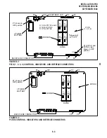
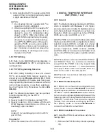
DC OUT TEST POINTS
DC OUT
PPSU56
D
D
PPSU56
-24V1-24V2 -24V3 DC OUT
POWER +5V -5V
BATT
+ _
SG FG LG FG
ON
OFF
AC IN
-24V
DG
+5V
DG
-5V
1
-24V
-24V2
3
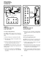
FIGURE 5-4
PPSU56 FRONT PANEL AND
DC OUT TEST POINTS
-24V4
-24V1
-24V3
ON
OFF
AC IN
POWER
-5V
+5V1
+5V 2
DC OUT
-24V5
-24V2
+5V 1
+5V2
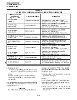
PPSU96
+
_
BATT
SG
FG
LG
FG
D
D
DC OUT
TEST
POINTS
PPSU96
DG
DG
DG
DG
DC OUT
+5V
-5V
2
2
-24V1
-24V3
-24V2
-24V4
-24V5
+5V
-5V
1
1
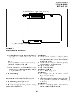
FIGURE 5-5
PPSU96 FRONT PANEL AND
DC OUT TEST POINTS
4.10 Power Supply Removal
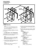
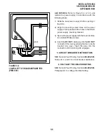
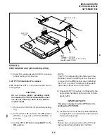
4.11 DK24. Refer to Figure 5-3 and remove the
power supply in accordance with the following
steps:
1) Remove screws (2) on right side of the KSU.
2) Slide the power supply out and gently remove
it from the KSU.
3) Reach behind the power supply and disconnect
the cable at the P1 backplane connector.
4.12 DK56/96. Refer to Figures 5-4 and 5-5 and
remove the power supply in accordance with the
following steps:
1) Squeeze the locking tab on the DC OUT plug,
and remove the plug from the DC OUT
connector.
2) Remove the four combination slotted/Phillips
mounting screws from the power supply front
panel.
3) Slide the power supply out.
4.20 Power Supply Replacement
4.21 DK24. Refer to Figure 5-3 and replace the
PPSU24 in accordance with the following steps:
1) Slide the power supply partially in to the right
end of the PCB slot shelf.
2) Reach behind the power supply, and connect
the cable from the rear of the power supply into
connector P1 on the KSU backplane.
3) Slide the power supply completely into the slot
and secure it with screws (2) on the right side of
the KSU.
Содержание Strata DK 24
Страница 2: ......
Страница 10: ......
Страница 12: ...INSTALLATION SYSTEM DESCRIPTION SECTION 400 096 202 SEPTEMBER 1992 ...
Страница 42: ......
Страница 72: ......
Страница 102: ......
Страница 110: ......
Страница 144: ...INSTALLATION TELEPHONE SECTION 400 096 207 SEPTEMBER 1992 ...
Страница 164: ......
Страница 166: ...INSTALLATION PERIPHERALS SECTION 400 096 208 SEPTEMBER 1992 ...
Страница 170: ......
Страница 238: ...INSTALLATION WIRING DIAGRAMS SECTION 400 096 209 SEPTEMBER 1992 ...
Страница 300: ......
Страница 302: ...REMOTE ADMINISTRATION MAINTENANCE PROCEDURES SECTION 400 096 600 SEPTEMBER 1992 ...
Страница 372: ......

