3-5
INSTALLATION-SITE REQUIREMENTS
SECTION 400-096-203
SEPTEMBER 1992
CAUTION!
If a reading of zero volts is obtained on
both voltage terminals (white wire to green
wire, black wire to green wire), the outlet is
not properly grounded. Omit steps 5 and
6, and proceed directly to step 7.
5) If a reading of zero volts on one terminal and
a reading of 100 ~ 120VAC on the other
terminal is obtained, remove both probes
from the outlet.
6) Set the meter to the “OHMS/Rx1” scale. Place
one probe on the ground terminal, and the
other probe on the terminal that produced a
reading of zero volts. The reading should be
less than one ohm.
CAUTION!
If the reading is more than one ohm, then
the outlet is not adequately grounded.
7) If the above tests show the outlet is not
properly grounded, the condition should be
corrected (per Article 250 of the National
Electrical Code) by a qualified electrician
before the system is connected.
5.20 Frame Ground Test
5.21 Use the following procedure to test the frame
ground conductor for continuity.
WARNING!
Hazardous voltages that may cause death
or injury may be exposed during the fol-
lowing test. Use great care when working
with AC power line voltage.
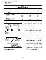
1) Refer to Figure 3-3.
2) Disconnect the AC plug of the system to
make sure that the two earth ground paths
are separated.
3) With a suitable volt/ohm meter, perform a
reading between points A and B shown in
Figure 3-3. Verify that the readings do not
exceed the figures listed below. If they do, the
condition must be corrected by a qualified
electrician before the system is connected.
A to B: 1 volt maximum
then
A to B: 1 ohm maximum
Содержание Strata DK 24
Страница 2: ......
Страница 10: ......
Страница 12: ...INSTALLATION SYSTEM DESCRIPTION SECTION 400 096 202 SEPTEMBER 1992 ...
Страница 42: ......
Страница 72: ......
Страница 102: ......
Страница 110: ......
Страница 144: ...INSTALLATION TELEPHONE SECTION 400 096 207 SEPTEMBER 1992 ...
Страница 164: ......
Страница 166: ...INSTALLATION PERIPHERALS SECTION 400 096 208 SEPTEMBER 1992 ...
Страница 170: ......
Страница 238: ...INSTALLATION WIRING DIAGRAMS SECTION 400 096 209 SEPTEMBER 1992 ...
Страница 300: ......
Страница 302: ...REMOTE ADMINISTRATION MAINTENANCE PROCEDURES SECTION 400 096 600 SEPTEMBER 1992 ...
Страница 372: ......


