INSTALLATION-KSU
SECTION 400-096-205
SEPTEMBER 1992
5-2
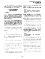
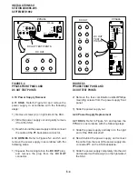
2) Lightly press all power supply circuit breakers
to ensure they have not accidentally opened
during shipment.
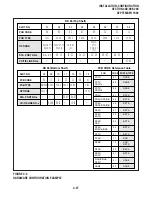
3) Set the power supply power switch to ON.
Ensure that the power supply indicators light as
follows:
•••••
DK24:
§
POWER indicator
§
-24V indicator
§
+5V indicator
§
-5V
indicator
§
-24V
1
~ V
2
(circuit breakers)
•••••
DK56:
§
POWER indicator
§
+5V indicator
§
-5V indicator
§
-24V
1
~ V
3
(circuit breakers)
•••••
DK96:
§
POWER indicator
§
-5V indicator
§
+5V
1
indicator
§
+5V
2
indicator
§
-24V
1
~ V
5
(circuit breakers)
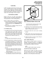
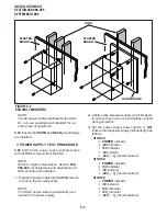
FIGURE 5-2
KSU WALL MOUNTING
STUD
HARD BOARD
PLASTER
BOARD
PLASTER
BOARD
NOTE:
The AC power must be dedicated to the KSU.
Do not use power/ground intended for an-
other piece of equipment.
2.32 Ensure that SG/FG and LG/FG ground straps
are installed.
3 POWER SUPPLY TEST PROCEDURE
3.00 Perform the power supply test procedure
with all PCBs removed from the KSU.
NOTE:
Refer to System Description, Section 200-
096-202
, for illustrations and descriptions of
KSU controls and indicators.
1) Plug the AC power cable into the AC IN connec-
tor and to the AC wall socket.
NOTE:
The DK24 power cable is permanently con-
nected to the power supply.
Содержание Strata DK 24
Страница 2: ......
Страница 10: ......
Страница 12: ...INSTALLATION SYSTEM DESCRIPTION SECTION 400 096 202 SEPTEMBER 1992 ...
Страница 42: ......
Страница 72: ......
Страница 102: ......
Страница 110: ......
Страница 144: ...INSTALLATION TELEPHONE SECTION 400 096 207 SEPTEMBER 1992 ...
Страница 164: ......
Страница 166: ...INSTALLATION PERIPHERALS SECTION 400 096 208 SEPTEMBER 1992 ...
Страница 170: ......
Страница 238: ...INSTALLATION WIRING DIAGRAMS SECTION 400 096 209 SEPTEMBER 1992 ...
Страница 300: ......
Страница 302: ...REMOTE ADMINISTRATION MAINTENANCE PROCEDURES SECTION 400 096 600 SEPTEMBER 1992 ...
Страница 372: ......


