4-5
INSTALLATION-CONFIGURATION
SECTION 400-096-204
SEPTEMBER 1992
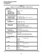
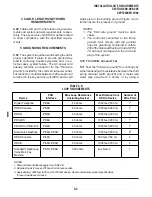
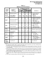
TABLE 4-C
UNIVERSAL SLOT/PCB CAPACITIES
• Electronic Telephones
• HDCB Door Phone Box
• HDSS Consoles
• BGM Source
• EOCU PCB for OCA
• Amplified Conference
• Standard Telephones
• Voice Mail Ports
• Fax
• Dictation Machine
• Off-premises Stations
• Other similar devices
Standard: Same as PSTU
Electronic: Same as PEKU
(see Note 3)
• Central Office
Loop Start Lines
• E&M TIE Lines
– Type I - Signaling
– 2 or 4 wire transmission
– Immediate start
See Table 4-D
2/Standard Telephone
4/Electronic Telephone
(Ports Standard/
Electronic)
8/Standard Telephone
(Ports, Standard)
4/CO Line
(Lines)
4/TIE Lines
(Lines)
See Table 4-F
(16)
(6/12)
1
(4)
(28)
1
(20)
(10/20)
1
(4)
(36)
(24/48)
1
(12)
(16/32)
PEKU
1
PSTU
PESU
3
(requires
PCTU2 and
above)
PCOU
PIOU,
5
PIOUS
or PEPU
PEMU
4
(8)
Printed
Circuit
Board
PCTU
PCTUS1
DK24
DK96
DK56
Interface to:
PCB Maximum Capacities
(Ports/Lines)
PCTU
PCTU
Circuits per
Printed
Circuit Board
(1/2/3/4) (1/2/3/4) (1/2/3/4)
8/Electronic Telephone
(Ports, Electronic)
(24)
(64)
(32)
(96)
3
4
8
12
(24)
(64)
(32)
(96)
3
4
8
12
3
5
12
8
4
7
5
9
1
1
3
2
• Digital Telephones
• DDSS Consoles
• PDIU-DI
• PDIU-DS
• DDCB Door Phone Box
8/Digital Telephone
(Ports, Digital)
(without PDIU-DI)
(with PDIU-DI)
PDKU
1
(requires
PCTU3
or PCTU4)
3
(24)
(N/A)
(N/A)
4
(32)
(32)
(21)
2
8
(64)
(64)
(53)
2
12
(96)
(96)
(80)
2
NOTES:
1. The appropriate capacities apply to digital and 6500-series electronic telephones only. If other Toshiba electronic
telephones (2000-, 3000-, 6000-) are used, refer to Worksheet 7.
2. The number of digital telephones with PDIU-DIs is limited by the system’s power capacity per Worksheet 7. Also, DIUs
are limited to slots 01 ~ 10 in DK96 and cannot be connected to Circuit 8 of a PDKU1 but can be connected to Circuit
1 of 8 of the PDKU2.
3. Normally only one PESU is installed in a system that requires a mix of standard and electronic telephone circuits. A PESU
is installed instead of a PSTU if only one or two standard telephone circuits are needed. It is installed instead of a PEKU
if only four electronic telephone circuits or less are needed. The PESU supports the same stations and options as the
PSTU and PESU do, except for the HDSS console.
4. The maximum number of PEMU PCBs is determined by the system's power supply capacity (caution: do not exceed the
numbers shown); also, if a PEMU is installed in a DK24 with a PCTUS1 PCB, only 16 station ports are available for
stations.
5. Only one type of peripheral interface PCB (PIOU, PIOUS, PEPU) may be installed per system.
Содержание Strata DK 24
Страница 2: ......
Страница 10: ......
Страница 12: ...INSTALLATION SYSTEM DESCRIPTION SECTION 400 096 202 SEPTEMBER 1992 ...
Страница 42: ......
Страница 72: ......
Страница 102: ......
Страница 110: ......
Страница 144: ...INSTALLATION TELEPHONE SECTION 400 096 207 SEPTEMBER 1992 ...
Страница 164: ......
Страница 166: ...INSTALLATION PERIPHERALS SECTION 400 096 208 SEPTEMBER 1992 ...
Страница 170: ......
Страница 238: ...INSTALLATION WIRING DIAGRAMS SECTION 400 096 209 SEPTEMBER 1992 ...
Страница 300: ......
Страница 302: ...REMOTE ADMINISTRATION MAINTENANCE PROCEDURES SECTION 400 096 600 SEPTEMBER 1992 ...
Страница 372: ......

