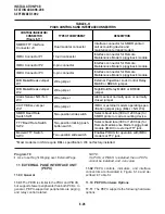
6-16
INSTALLATION-PCB
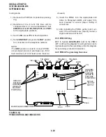
SECTION 400-096-206
SEPTEMBER 1992
NOTE:
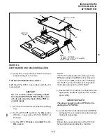
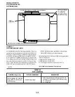
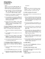
PESU connectors P10, P20, P40, P50, and
P60 are positioned to allow installation of the
EOCU only in the proper position (Figure 6-8).
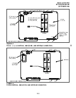
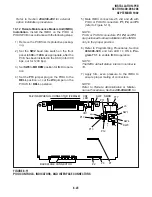
2) Mate the EOCU connectors J10, J20, J40,
J50, and J60 (Figure 6-6) with the PESU
connectors P10, P20, P40, P50, and P60.
3) Apply firm, even pressure to the EOCU to
ensure proper mating of connectors.
4) Use 3-pair cable for connecting the PESU and
the OCA electronic telephone (refer to Wiring
Diagrams, Section 400-096-209, for wiring/
interconnecting details).
5) Refer to Telephone Installation, Section 400-
096-207, for procedures to add required OCA
upgrade (HVSU2 or HVSU/HVSI) to elec-
tronic telephones.
7.13 Door Phone/Lock Control Unit (HDCB)
Configuration. Configure the PESU to support an
HDCB in accordance with the following steps:
1) Remove the PCB from its protective packag-
ing.
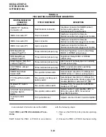
2) Cut the W9 Door Phone jumper wire on the
PESU PCB.
3) Refer to Telephone Installation, Section 400-
096-207, for installation procedures for the
HDCB and associated door phones (MDFBs).
4) Each HDCB requires dedicated use of Circuit
5 of a particular PESU PCB.
7.14 Background Music Configuration. Config-
ure the PESU to support a separate background
music source in accordance with the following
steps:
1) Remove the PEKU PCB from its protective
packaging.
2) Cut the W7 (BGM) jumper wire on the PCB.
3) Refer to Peripherals Installation, Section 400-
096-208, for installation procedures for BGM
connection.
NOTE:
With PCTU2 or PCTUS, the PESU must be
installed in Slot 01 to support BGM. With
PCTU3 and PCTU4, it can be in any slot.
7.20 PESU Installation Procedures
7.21 Install the PESU in accordance with the fol-
lowing steps:
1) Remove the PCB from its protective packag-
ing. The protective shield on the back of the
PESU is designed to protect the installer from
potentially hazardous ring voltage. Do not
remove this shield.
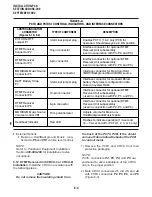
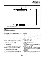
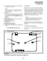
2) Ensure that the PESU subunit (ESTS) is se-
curely attached to the PESU (refer to Figure 6-
8).
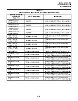
3) Ensure the PESU has been configured for the
appropriate hardware options (refer to Para-
graph 7.10).
4) Ensure that the ring voltage option, P90, is set
to the “H” position for initial installation. The “L”
position is used if devices connected to the
PESU experience ring-trip.
5) Insert the PESU into the appropriate slot, and
apply firm, even pressure to ensure proper
mating of connectors.
6) After installing the PESU, gently pull the PCB
outward. If the connectors are properly mated,
a slight resistance will be felt.
7.30 PESU Wiring
7.31 Refer to Section 400-096-209, for PESU wir-
ing/interconnecting details.
7.40 PESU Programming Overview
7.41 The following programming parameters may
be specified for the PESU:
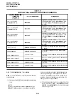
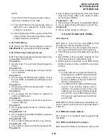
Program 03
•
Specify Code 25 for all slots that have PESUs
without an EOCU.
Содержание Strata DK 24
Страница 2: ......
Страница 10: ......
Страница 12: ...INSTALLATION SYSTEM DESCRIPTION SECTION 400 096 202 SEPTEMBER 1992 ...
Страница 42: ......
Страница 72: ......
Страница 102: ......
Страница 110: ......
Страница 144: ...INSTALLATION TELEPHONE SECTION 400 096 207 SEPTEMBER 1992 ...
Страница 164: ......
Страница 166: ...INSTALLATION PERIPHERALS SECTION 400 096 208 SEPTEMBER 1992 ...
Страница 170: ......
Страница 238: ...INSTALLATION WIRING DIAGRAMS SECTION 400 096 209 SEPTEMBER 1992 ...
Страница 300: ......
Страница 302: ...REMOTE ADMINISTRATION MAINTENANCE PROCEDURES SECTION 400 096 600 SEPTEMBER 1992 ...
Страница 372: ......

