INSTALLATION-SYSTEM DESCRIPTION
SECTION 400-096-202
SEPTEMBER 1992
2-4
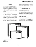
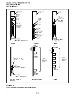
FIGURE 2-4—DK96 KSU INTERIOR
-24V
4
-24V
1
-24V
3
ON
OFF
PCTU
S09
S10
S11
S12
S13
S14
FG
PCTU
AC IN
POWER
-5V
+5V
1
+5V2
DC OUT
-24V
5
-24V
2
+5V
1
+5V2
PPSU96
+
_
BATT
SG
FG
LG
FG
1
6
S01
S02
S03
S04
S05
S06
S07
S08
D
D
PCB SLOTS
CONNECTOR
POWER
SUPPLY
same vertical position on the KSU’s backplane.
This standardization enables any of the optional
PCBs to be installed in any slot. The PCTU slot
incorporates the same 40-pin female connector,
but it is set 0.25-inch higher, so that only a PCTU
PCB may be installed in the slot.
3.23 The power supply is factory-installed,
mounted horizontally above the PCB shelf, and is
secured with four combination slotted/Phillips
mounting screws.
3.30 DK96 KSU Interior
3.31 The DK96 cabinet interior has two shelves
(Figure 2-4). The top shelf has eight available PCB
slots labeled S01 ~ S08. The bottom shelf has
seven available PCB slots labeled PCTU and S09
~ S14. Only the PCTU slot serves a dedicated
function.
3.32 PCB slots S01 ~ S14 each incorporates a
standard 40-pin female connector located in the
same vertical position on the KSU’s backplane.
This standardization enables any of the optional
PCBs to be installed in any available slot. The
PCTU slot incorporates the same 40-pin female
connector, but it is set 0.25-inch higher, so that
only a PCTU PCB may be installed in the slot.
3.33 The power supply is factory-installed,
mounted vertically to the right of the two PCB
shelves, and is secured with four combination
slotted/Phillips mounting screws.
4 POWER SUPPLIES
4.00 STRATA DK systems incorporate single-
chassis, switching-type power supplies. The power
supplies for the three models are functionally iden-
tical (except for power capacity), although they
differ in appearance due to cabinet sizes and
mounting considerations. The DK24 model uses a
PPSU24 power supply (Figure 2-5), DK56 uses a
PPSU56 (Figure 2-6), and DK96 uses a PPSU96
(Figure 2-7).
Содержание Strata DK 24
Страница 2: ......
Страница 10: ......
Страница 12: ...INSTALLATION SYSTEM DESCRIPTION SECTION 400 096 202 SEPTEMBER 1992 ...
Страница 42: ......
Страница 72: ......
Страница 102: ......
Страница 110: ......
Страница 144: ...INSTALLATION TELEPHONE SECTION 400 096 207 SEPTEMBER 1992 ...
Страница 164: ......
Страница 166: ...INSTALLATION PERIPHERALS SECTION 400 096 208 SEPTEMBER 1992 ...
Страница 170: ......
Страница 238: ...INSTALLATION WIRING DIAGRAMS SECTION 400 096 209 SEPTEMBER 1992 ...
Страница 300: ......
Страница 302: ...REMOTE ADMINISTRATION MAINTENANCE PROCEDURES SECTION 400 096 600 SEPTEMBER 1992 ...
Страница 372: ......

