4-17
INSTALLATION-CONFIGURATION
SECTION 400-096-204
SEPTEMBER 1992
CONFIGURATION GUIDE, WORKSHEET 3
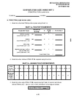
C. PSTU PCBs (eight station ports)
Actual PSTU PCBs = (CT1)
(PSTU/PESU PCB requirements)
1. Determine the total PSTU ports required using Chart 3.
CHART 3—PSTU PORT REQUIREMENTS
Equipment Type:
Equipment
Quantity
X
Ports
=
Ports Used
Standard telephones:
(see Worksheet 1, C1)
Other devices:
(see Worksheet 1, C2)
(C1)
(C2)
X
X
1
1
=
=
=
.
.
.
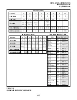
2. Determine the actual PSTU PCB requirements using Chart 4.
CHART 4—ACTUAL PSTU PCB REQUIREMENTS
Total
Ports
(Chart 3)
PSTU
PCBs
01 ~ 08 09 ~ 16 17 ~ 24 25 ~ 32 33 ~ 40 41 ~ 48 49 ~ 56 57 ~ 64 65 ~ 72 73 ~ 80 81 ~ 88 89 ~ 96
1
2
3
4
5
6
7
8
9
10
11
12
3. PESU: In a configuration requiring less than two PSTU station ports, a PESU PCB can be used
in place of a PSTU PCB. Normally, only one PESU is installed in a system.
Total PSTU Ports
Actual PESU PCBs = (CT2)
NOTE:
The PCTU or PCTUS1 must be equipped with a CRCU (4 or 8) to translate DTMF signals
generated by most devices that interface with standard telephone ports.
Содержание Strata DK 24
Страница 2: ......
Страница 10: ......
Страница 12: ...INSTALLATION SYSTEM DESCRIPTION SECTION 400 096 202 SEPTEMBER 1992 ...
Страница 42: ......
Страница 72: ......
Страница 102: ......
Страница 110: ......
Страница 144: ...INSTALLATION TELEPHONE SECTION 400 096 207 SEPTEMBER 1992 ...
Страница 164: ......
Страница 166: ...INSTALLATION PERIPHERALS SECTION 400 096 208 SEPTEMBER 1992 ...
Страница 170: ......
Страница 238: ...INSTALLATION WIRING DIAGRAMS SECTION 400 096 209 SEPTEMBER 1992 ...
Страница 300: ......
Страница 302: ...REMOTE ADMINISTRATION MAINTENANCE PROCEDURES SECTION 400 096 600 SEPTEMBER 1992 ...
Страница 372: ......


