8-29
INSTALLATION-PERIPHERALS
SECTION 400-096-208
SEPTEMBER 1992
•
K1/zone 1 = 35
•
K2/zone 2 = 36
•
K3/zone 3 = 37
•
K4/zone 4 = 38
•
All zones = 39
NOTE:
Multi-zone page output rating is 30W/maxi-
mum at 300 ohms.
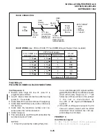
6.14 An all zone page code (39) is also available as
an option (see Program 10-2). When the all page
code is dialed, all four relays are activated to permit
simultaneous paging to all speaker zones and all
digital and electronic telephone speakers. Install
this option in accordance with the following steps:
(Refer to Figure 8-18.)
1) Connect the input from the paging amplifier to
Pins 13 (SPR) and 38 (SPT) of the PIOU.
2) Connect the BGM music source to the music
amplifier input.
3) Connect the paging amplifier output to the “M”
contact’s PIOU Relays K1 ~ K4 and the “C”
terminal of Zone 1 ~ Zone 4 speakers.
4) Connect the BGM music amplifier output to
Terminal 23 (PG COMMON) of the PIOU, and
to Zone 1 ~ Zone 4 speakers.
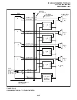
6.15 Zone Page with BGM (multiple amplifiers).
This configuration also provides multiple-zone pag-
ing capability, as in Paragraph 6.13. However,
separate amplifiers are used for each zone. Install
this option in accordance with the following steps:
(Refer to Figure 8-19.)
1) Connect the inputs from the paging amplifiers
to Pins 13 (SPR) and 38 (SPT) of the PIOU.
2) Connect the music source to the music ampli-
fier input.
3) Connect the paging amplifier outputs to PIOU
Relays K1 ~ K4 and Zone 1 ~ Zone 4 speak-
ers.
4) Connect the music amplifier output to Termi-
nal 23 (PG COMMON) of the PIOU, and to the
“C” terminal of Zone 1 ~ Zone 4 speakers.
5) Connect Zone 1 ~ Zone 4 speakers “A” termi-
nal to the “B” contact of the PIOU Relays K1 ~
K4, respectively.
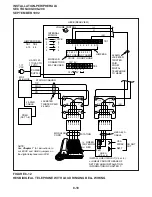
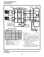
6.16 Simultaneous Night Ringing over External
Page Zones (PIOU only): Incoming calls during
the NIGHT mode will ring all external page zones
simultaneously with this feature. Install the paging
amplifier in accordance with the following steps
(Figure 8-20)—Steps 1 ~ 6 are performed at the
MDF:
NOTE:
See Paragraph 6.17 for night ringing over
selected external page zones.
1) Cross-connect the amplifier input to Pins 13
(SPR) and 38 (SPT) of the PIOU PCB.
2) Cross-connect the amplifier Output A to the
PGIN 1 ~ PGIN 4 connector from the PIOU.
3) Cross-connect the amplifier Output B to the
Zone 1 ~ Zone 4 speaker common line.
4) Cross-connect the PIOU PGOUT 1 ~
PGOUT 4 to Zone 1 ~ Zone 4 speakers.
5) Cross-connect the amplifier Output A to Pin 9
(NHR) of the PIOU.
6) Cross-connect a jumper from Pin 34 (NHT) to
Pin 23 (PG COMMON) from the PIOU PCB.
7) In Program 77-1, set LED 05 to OFF and 06
to ON. Set LED 08 to ON if door phones are to
ring over external page when the system is in
NIGHT mode.
8) In Program 78, enable the CO lines that are to
ring via external page when the system is set
in the NIGHT mode.
9) In Program 39, assign the Night Transfer
buttons to digital and electronic telephones
per the System Record Sheets (see Note).
Содержание Strata DK 24
Страница 2: ......
Страница 10: ......
Страница 12: ...INSTALLATION SYSTEM DESCRIPTION SECTION 400 096 202 SEPTEMBER 1992 ...
Страница 42: ......
Страница 72: ......
Страница 102: ......
Страница 110: ......
Страница 144: ...INSTALLATION TELEPHONE SECTION 400 096 207 SEPTEMBER 1992 ...
Страница 164: ......
Страница 166: ...INSTALLATION PERIPHERALS SECTION 400 096 208 SEPTEMBER 1992 ...
Страница 170: ......
Страница 238: ...INSTALLATION WIRING DIAGRAMS SECTION 400 096 209 SEPTEMBER 1992 ...
Страница 300: ......
Страница 302: ...REMOTE ADMINISTRATION MAINTENANCE PROCEDURES SECTION 400 096 600 SEPTEMBER 1992 ...
Страница 372: ......

