


6-4
INSTALLATION-PCB
SECTION 400-096-206
SEPTEMBER 1992
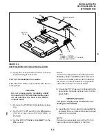
the back of the PCTU PCB. If the shield
comes off, do not allow the back of the PCB
to contact metal.
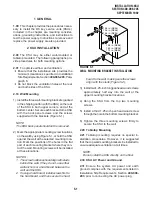
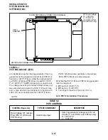
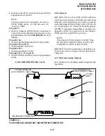
1) Remove the PCTU and CRCU from their
protective packaging.
NOTE:
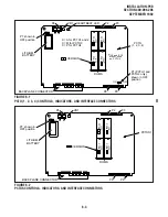
PCTU connectors P2, P3, P8, and P9 are
positioned to allow installation of the CRCU
only in the proper position.
2) Mate CRCU connectors J1, J2, J3, and J4
with PCTU connectors P2, P3, P8, and P9
(Figure 6-3).
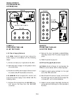
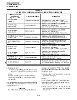
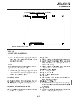
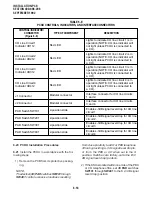
TABLE 6-A
PCTU AND PCTUS1 CONTROLS, INDICATORS, AND INTERFACE CONNECTORS
CONTROL/INDICATOR/
CONNECTOR
(Figures 6-1 & 6-2)
TYPE OF COMPONENT
DESCRIPTION
PCTU ON/OFF
Jumper P1
3-terminal jumper plug
Enables PCTU (1 & 2 only) PCB for
operation. Should always be in ON position.
MOH/BGM Music Source
Connector P6
Interface connector for Music-on-Hold
(MOH)/Background Music(BGM) source.
2-terminal connector
BATT Battery Strap
P7
3-terminal jumper plug
Interface connector for on-board lithium
battery that protects configuration data
stored in system RAM.
DTMF Receiver
Connector P8
10-pin connector
Interface connector for optional DTMF
Receiver Unit subassembly
(used in conjunction with P2, P3, and P9).
DTMF Receiver
Connector P9
6-pin connector
MOH/BGM Music Source
Volume Control VR1
Adjusts volume for Music-on-
Hold/Background Music feature.
Trim potentiometer
DTMF Receiver
Connector P2
10-pin connector
Interface connector for optional DTMF
Receiver Unit subassembly
(used in conjunction with P3, P8, and P9).
DTMF Receiver
Connector P3
6-pin connector
Interface connector for optional DTMF
Receiver Unit subassembly
(used in conjunction with P2, P8, and P9).
Interface connector for optional DTMF
Receiver Unit subassembly
(used in conjunction with P2, P3, and P8).
Heartbeat Indicator
Flashes to indicate operation (1/4-second
on—1/4-second off); (PCTU1, 2, 3, or 4 only).
Red LED
•
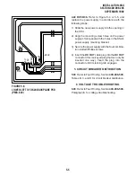
External Options
§
Music-on-Hold/Background Music (con-
nected to P6 and VR1 volume level control)
NOTE:
Refer to Peripheral Equipment Installation,
Section 400-096-208, for installation of exter-
nal options.
3.12 DTMF Receiver Unit (CRCU-4 or CRCU-8)
Installation. Install the CRCU in accordance with
the following steps:
CAUTION!
Do not remove the insulating shield from
Содержание Strata DK 24
Страница 2: ......
Страница 10: ......
Страница 12: ...INSTALLATION SYSTEM DESCRIPTION SECTION 400 096 202 SEPTEMBER 1992 ...
Страница 42: ......
Страница 72: ......
Страница 102: ......
Страница 110: ......
Страница 144: ...INSTALLATION TELEPHONE SECTION 400 096 207 SEPTEMBER 1992 ...
Страница 164: ......
Страница 166: ...INSTALLATION PERIPHERALS SECTION 400 096 208 SEPTEMBER 1992 ...
Страница 170: ......
Страница 238: ...INSTALLATION WIRING DIAGRAMS SECTION 400 096 209 SEPTEMBER 1992 ...
Страница 300: ......
Страница 302: ...REMOTE ADMINISTRATION MAINTENANCE PROCEDURES SECTION 400 096 600 SEPTEMBER 1992 ...
Страница 372: ......


