2-1
INSTALLATION-SYSTEM DESCRIPTION
SECTION 400-096-202
SEPTEMBER 1992
1 GENERAL
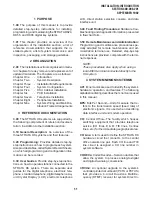
1.00 This chapter provides an overview of the
technology employed in the STRATA DK system
design and a detailed description of the system
hardware, including the basic equipment cabinet
(key service unit), printed circuit board (PCB)
options, and system peripheral equipment. A de-
scription of system controls and indicators is also
provided.
1.10 System Description
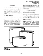
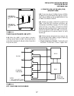
1.11 The main unit of each STRATA DK system is
the KSU (Figure 2-1), which houses the power
supply and a number of slots which can support a
number of optional PCBs, to which stations and
peripherals are connected. The quantity and type
of PCBs, stations, and peripherals installed de-
pends on the user’s requirements. The primary
differences between the STRATA DK systems are
KSU sizes, PCB capacities, and power supplies.
1.12 Hardware for all three system types is iden-
tical, with the exception of the KSUs and power
supplies. Differences between models are identi-
fied, as applicable.
2 SYSTEM TECHNOLOGY
2.00 Custom Electronic Circuitry
2.01 STRATA DK system circuitry employs Large
Scale Integration (LSI) technology to increase
system efficiency, while allowing a reduction in
physical size. Use of CMOS circuits, when appli-
cable, minimizes the system’s power requirements.
2.10 Microprocessors
2.11 Main Microprocessor. The STRATA DK
systems employ a 16-bit, 68000-type micropro-
cessor, which operates at a speed of 8 MHz, for
stored program control. The main microprocessor
FIGURE 2-1
DK24/56/96 KSUs
Strata
DK96
TOSHIBA
Strata
DK56
TOSHIBA
TOSHIBA
DK24
Strata
Содержание Strata DK 24
Страница 2: ......
Страница 10: ......
Страница 12: ...INSTALLATION SYSTEM DESCRIPTION SECTION 400 096 202 SEPTEMBER 1992 ...
Страница 42: ......
Страница 72: ......
Страница 102: ......
Страница 110: ......
Страница 144: ...INSTALLATION TELEPHONE SECTION 400 096 207 SEPTEMBER 1992 ...
Страница 164: ......
Страница 166: ...INSTALLATION PERIPHERALS SECTION 400 096 208 SEPTEMBER 1992 ...
Страница 170: ......
Страница 238: ...INSTALLATION WIRING DIAGRAMS SECTION 400 096 209 SEPTEMBER 1992 ...
Страница 300: ......
Страница 302: ...REMOTE ADMINISTRATION MAINTENANCE PROCEDURES SECTION 400 096 600 SEPTEMBER 1992 ...
Страница 372: ......

