


5-3
INSTALLATION-KSU
SECTION 400-096-205
SEPTEMBER 1992
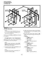
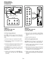
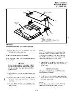
1) Loosen the four screws holding the panel on
the back of the KSU.
2) Lift the panel up and pull it off of the KSU.
3) On the lower left side of the backplane PCB
(PMB-824), the test points for the various volt-
ages are marked. Refer to Figure 5-6.
4) Using the multimeter (set to the appropriate
range), measure the voltages at the desig-
nated test points.
NOTE:
The multimeter test probes must have sharp
tips to penetrate solder mask on backplane
PCB.
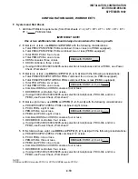
4 POWER SUPPLY REMOVAL AND
REPLACEMENT
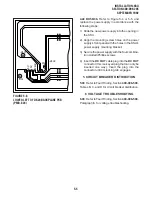
4.00 The following paragraphs provide procedures
necessary to remove and replace faulty power
supplies.
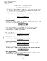
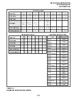
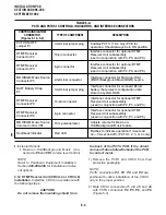
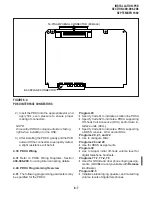
4) Using a multimeter (set to the appropriate range),
measure the voltages at the pins of the DC OUT
connector for DK56/DK96 or the P1 backplane
connector for DK24 as shown in Figures 5-3, 5-
4, or 5-5. Ensure that the voltages fall within the
ranges specified. If a measured voltage falls
outside of the acceptable range, remove the
DC power plug from the power supply DC OUT
connector (DK56/96) or P1 backplane connec-
tor (DK24) and measure again. If a measured
voltage is still unacceptable, replace the power
supply. (Refer to Paragraph 4.)
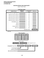
DC Voltage
Range Specifications
-24V:
-26.3 ~ -27.8
-5V:
-4.5 ~
-5.5
+5V:
+4.5 ~
+5.5
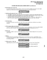
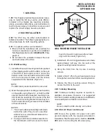
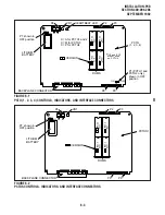
3.01 To test the power supply voltages with all
circuit boards installed, install the circuit boards
and use the procedure in Paragraph 3.00 for the
PPSU56/96. Use the following procedure to test
the PPSU24.
+
_
BATT
FG
LG
FG
-24V1 -24V2
FG
LG
PPSU 24
POWER
-5V
+5V
-24V
OUT
AC LINE
ON
OFF
GRN
YEL
YEL
RED
BLUE
GRN
CABLE FROM REAR
OF POWER SUPPLY
CIRCUIT
BREAKER
MOUNTING
SCREWS ON
RIGHT SIDE
VOLTAGE
LED's
BATTERY
CONNECTOR
AC POWER
CORD
P1
BACKPLANE
KSU (FRONT VIEW)
TEST POINTS
FG
-24V
-5V
-24V
+5V
DG
CONNECTOR
2
1
POWER
SWITCH
CAUTION
BEFORE CONNECTING THE AC PLUG
WITH PLUG SOCKET, BE SURE TO
FIT THE POWER UNIT TO THE
CABINET. IF AC PLUG IS INSERTED
TO THE PLUG SOCKET AT POWER
WHEN THE POWER SOURCE IS
DISCONNECTED WITH THE
CABINET FOR EXCHANGING OF
POWER UNITS, BE SURE TO
TURN OFF THE POWER SWITCH
AND PULL OUT THE AC PLUG
FROM THE PLUG SOCKET BEFORE
DOING SO.
UNIT AND ANY INTERNAL PART
IS TOUCHED, AN ELECTRIC SHOCK
ACCIDENT MIGHT DEVELOP.
FIGURE 5-3
PPSU24 FRONT PANEL AND DC OUT TEST POINTS
Содержание Strata DK 24
Страница 2: ......
Страница 10: ......
Страница 12: ...INSTALLATION SYSTEM DESCRIPTION SECTION 400 096 202 SEPTEMBER 1992 ...
Страница 42: ......
Страница 72: ......
Страница 102: ......
Страница 110: ......
Страница 144: ...INSTALLATION TELEPHONE SECTION 400 096 207 SEPTEMBER 1992 ...
Страница 164: ......
Страница 166: ...INSTALLATION PERIPHERALS SECTION 400 096 208 SEPTEMBER 1992 ...
Страница 170: ......
Страница 238: ...INSTALLATION WIRING DIAGRAMS SECTION 400 096 209 SEPTEMBER 1992 ...
Страница 300: ......
Страница 302: ...REMOTE ADMINISTRATION MAINTENANCE PROCEDURES SECTION 400 096 600 SEPTEMBER 1992 ...
Страница 372: ......


