-3-
STRATA DK FAULT FINDING
SECTION 400-096-500
SEPTEMBER 1992
7
STATION CABLE CONTINUITY CHECK
7.01 Voltmeter Test
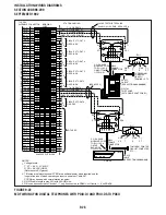
7.02 The continuity of the cable run between the
HKSU and the digital or electronic telephone is
checked with a voltmeter as follows:
NOTE:
Perform the following at the locations indicated:
1. Modular block: Check all stations cables
2. MDF: Check cable from KSU to MDF.
3. These tests also apply for troubleshooting cable
problems with HDCB, DDCB, and PDIU-DS de-
vices.
1) Disconnect the digital or electronic telephone.
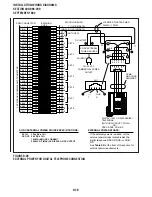
2) Using a DC voltmeter, measure between the
wires of the two pairs to verify the readings
shown in Table E for electronic telephone
ports (PEKU or PESU). Refer to Table G for
digital telephone ports. The reading will be a
plus or minus depending on meter lead place-
ment.
3) An improper reading indicates an open,
crossed or shorted wire.
Circuit
Breaker
TABLE D
DK96 CIRCUIT BREAKER DISTRIBUTION
+5V1
+5V2
Ð24V1
Ð24V2
Ð24V3
Ð24V4
Ð24V5
Backplane PCB
(lower)
PCTU
All Slots
Slot 01, 02
Slot 03, 04, 05
Slot 06, 07, 08
+5V
Ð5V
Ð
Ð
Ð
Ð
Ð
Backplane PCB
(upper)
All Slots
Slot 09, 10, 11
Slot 12, 13, 14
Ð
Ð
Ð
Ð
Ð
Ð
Ð
NOTE:
+5 volts goes to all PCB slots.
-5 volts goes to all PCB slots.
NOTE:
+5 volts goes to all PCB slots.
-5 volts goes to all PCB slots.
can be employed to further isolate possible causes
before removal of the KSU back cover or the power
supply unit. Figure 2 shows backplane connector
P1 and P4 and voltages at each pin. Voltages
should fall within the following ranges:
Nominal
Range
-24v
-26.3 ~ -27.8
+5v
+4.5 ~ +5.5
-5v
-4.5 ~ -5.5
6.02 If voltage checks indicate a power supply
fault, replace the power supply with a correctly
operating unit. Refer to Section 400-096-200,
Installation, for power supply installation
procedures.
6.03 The circuit breaker distribution chart show
which voltages supply the various slot locations. If
a circuit breaker pops out, this chart will help to
identify a malfunctioning PCB (reference Tables
B, C, and D).
Circuit
Breaker
TABLE B
DK24 CIRCUIT BREAKER DISTRIBUTION
-24V1
-24V2
+5V
-5V
PCTUS
Slot 01, 02, 03
Slot 04, 05, 06
All slots
All slots
Ñ
Ñ
+5V
-5V
Backplane PCB
Circuit Breaker
TABLE C
DK56 CIRCUIT BREAKER DISTRIBUTION
Ð24V1
Ð24V2
Ð24V3
Backplane PCB
PCTU
Slots 01, 02
Slots 03, 04, 05
Slots 06, 07, 08
Ð
Ð
Ð
Содержание Strata DK 24
Страница 2: ......
Страница 10: ......
Страница 12: ...INSTALLATION SYSTEM DESCRIPTION SECTION 400 096 202 SEPTEMBER 1992 ...
Страница 42: ......
Страница 72: ......
Страница 102: ......
Страница 110: ......
Страница 144: ...INSTALLATION TELEPHONE SECTION 400 096 207 SEPTEMBER 1992 ...
Страница 164: ......
Страница 166: ...INSTALLATION PERIPHERALS SECTION 400 096 208 SEPTEMBER 1992 ...
Страница 170: ......
Страница 238: ...INSTALLATION WIRING DIAGRAMS SECTION 400 096 209 SEPTEMBER 1992 ...
Страница 300: ......
Страница 302: ...REMOTE ADMINISTRATION MAINTENANCE PROCEDURES SECTION 400 096 600 SEPTEMBER 1992 ...
Страница 372: ......

