8-21
INSTALLATION-PERIPHERALS
SECTION 400-096-208
SEPTEMBER 1992
following installation procedures for the system
hardware requirements for each option:
5.20 HESB Option Installation
5.21 Loud Ringing Bell Installation. Install the
HESB Loud Ringing Bell option in accordance with
the following procedures:
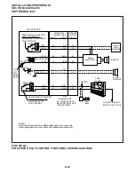
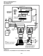
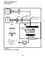
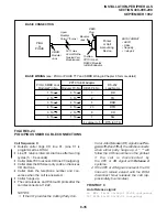
HESB Installation for Digital Telephone (Figure
8-12):
1) Connect a jumper between Terminals 2 and
10 on the HESB TB1 terminal block.
2) Connect a jumper between Terminals 4 and 5
on the HESB TB2 terminal block.
NOTES:
1. HESB connections made in steps 3~ 5
may be accomplished using the HESB
VOICE modular jack instead of the TB1
terminal block.
2. Install an HHEU PCB and HESC-65A cable
in the telephone per Section 400-096-207
before proceeding with Step 3.
3) Connect Terminal 1 of the HESB TB1 terminal
block to the red (+) wire of the HESC-65A
using a modular block.
4) Connect Terminal 2 of the HESB TB1 terminal
block to the green (-) wire of the HESC-65A
using a modular block.
5) Connect Terminal 8 of the HESB TB1 terminal
block to the yellow (L2) wire of the HESC-65A
cable using a modular block.
6) Connect the HACU-120 power supply’s +12V
lead to Terminal 1 of the HESB TB2 terminal
block, and connect the power supply’s 0V lead
to Terminal 2.
7) Plug the provided power cord into the power
supply and to a 117VAC, 60Hz power source.
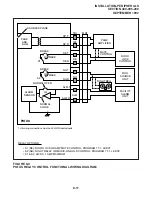
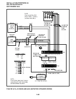
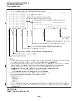
HESB Installation for Electronic Telephone (Fig-
ure 8-13):
1) On the HESB TB1 terminal block: connect a
jumper between Terminals 6 and 7, and con-
nect another jumper between Terminals 5 and
8.
2) On the HESB TB2 terminal block, connect a
jumper between Terminals 4 and 5 .
NOTES:
1. HESB connections made in steps 3~ 6
may be accomplished using the HESB
VOICE modular jack instead of the TB1
terminal block.
2. Install an HHEU PCB and HESC-65 (or
HESC-65A) cable in the telephone per
Chapter 7 before proceeding with Step 3.
3) Connect Terminal 1 of the HESB TB1 terminal
block to the red (+) wire of the HESC-65 cable
using a modular block.
4) Connect Terminal 2 of the HESB TB1 terminal
block to the green (-) wire of the HESC-65
cable using a modular block.
5) Connect Terminal 3 of the HESB TB1 terminal
block to pin 3 of the electronic telephone's
modular block (VOICE TIP).
6) Connect Terminal 4 of the HESB TB1 terminal
block to Pin 4 of the electronic telephone's
modular block (VOICE RING).
7) Connect the HACU-120 power supply’s +12V
lead to Terminal 1 of the HESB TB2 terminal
block, and connect the power supply’s 0V lead
to Terminal 2.
8) Plug the provided power cord into the power
supply and to a 117VAC, 60Hz power source.
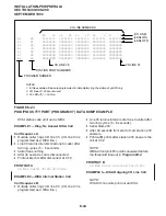
5.22 Loud Ringing Bell Test. Test the Loud Ring-
ing Bell installation in accordance with the follow-
ing steps:
1) Make a CO or station call to the station config-
ured for the loud ringing bell.
•
Ringing will be heard over the HESB.
2) Using a small slotted screwdriver, adjust the
HESB volume control to the desired level by
turning the volume control on the back of the
Содержание Strata DK 24
Страница 2: ......
Страница 10: ......
Страница 12: ...INSTALLATION SYSTEM DESCRIPTION SECTION 400 096 202 SEPTEMBER 1992 ...
Страница 42: ......
Страница 72: ......
Страница 102: ......
Страница 110: ......
Страница 144: ...INSTALLATION TELEPHONE SECTION 400 096 207 SEPTEMBER 1992 ...
Страница 164: ......
Страница 166: ...INSTALLATION PERIPHERALS SECTION 400 096 208 SEPTEMBER 1992 ...
Страница 170: ......
Страница 238: ...INSTALLATION WIRING DIAGRAMS SECTION 400 096 209 SEPTEMBER 1992 ...
Страница 300: ......
Страница 302: ...REMOTE ADMINISTRATION MAINTENANCE PROCEDURES SECTION 400 096 600 SEPTEMBER 1992 ...
Страница 372: ......


