8-38
INSTALLATION-PERIPHERALS
SECTION 400-096-208
SEPTEMBER 1992
and testing to be accomplished. An IMDU modem
or an external maintenance modem (300 or 1200
baud full-duplex) can be connected to allow system
programming and testing to be accomplished from
a remote location.
NOTE:
An external modem is required for Remote
Maintenance if an IMDU is not installed on the
PIOU or PIOUS. The IMDU has a built-in
maintenance channel for remote connection;
however, an external modem requires a CO
line or a standard telephone port on a PSTU or
PESU.
9.10 Maintenance Terminal/External Modem
Option System Hardware Requirements
9.11 The STRATA DK system must be equipped
with a PIOU or PIOUS PCB to support the mainte-
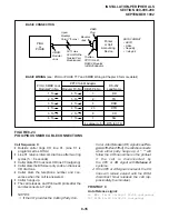
nance terminal/external modem options. Connect-
ing the maintenance terminal or external mainte-
nance modem to the PIOU or PIOUS PCB is
accomplished with a standard 3-pair modular cord
and a PPTC adaptor connected to the PIOU or
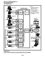
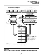
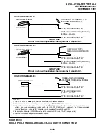
PIOUS TTY jack. (Refer to Figure 8-25.)
NOTE:
If the IMDU modem is used, the PPTC adapter
or modular cord is not required.
9.20 Local Maintenance Terminal Installation
9.21 Install the ASCII terminal in accordance with
the following steps: (Refer to Figure 8-25.)
1) Connect the 3-pair modular cable (or 24 AWG
twisted pairs) and the PPTC adaptor from the
PIOU or PIOUS TTY port to the remote main-
tenance terminal DB25 connector.
2) Set the PIOU or PIOUS SW2 switch to match
the modem or terminal baud rate:
•
Push in for 300 bps (baud rate indicator
CD4 is lighted); let out (by pushing again)
for 1200 bps (CD4 is not lighted).
3) Set the PIOU or PIOUS SW3 switch to the
TTY position.
4) Set the P13 jumper plug on the PIOU to the
BELL configuration, or cut the W4 jumper on
the PIOUS (also for BELL configuration).
NOTE:
The P13 (PIOU) and W4 (PIOUS) CCITT
configurations are not normally used in the
USA.
5) Set the terminal to 7-bits/even parity/1 stop
bit.
6) Programming and system testing, via the main-
tenance terminal, is described in the Remote
Maintenance Procedures, Section 400-096-
600.
NOTE:
If the telephone connected to Port 05 is in the
program mode, programming from the main-
tenance terminal is not allowed.
9.30 Remote Maintenance Option Installation
9.31 IMDU Maintenance Modem. The IMDU mo-
dem mounts on the PIOU or PIOUS PCB and
provides 300 or 1200 bps, full-duplex communi-
cation for remote maintenance. If the IMDU is
employed, a dedicated CO line, PSTU, or PESU
connection is not required. Connection of the
remote maintenance terminal is through existing
system CO lines via intercom Number 19. Refer
to the PIOU or PIOUS portion of Section 400-
096-206 for details on hardware installation and
programming requirements. Remote Mainte-
nance Procedures, Section 400-096-600, pro-
vides more information about using the IMDU for
remote maintenance.
9.32 External Maintenance Modem Installation.
Install the external modem in accordance with the
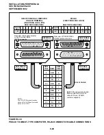
following steps: (Refer to Figure 8-25.)
NOTE:
The Toshiba PPTC RS-232 modular-to-DB25
adaptor is factory-configured for ASCII termi-
nal connection. Pins 2 and 3 and pins 8 and 20
of the adaptor must be reversed for external
modem connection.
Содержание Strata DK 24
Страница 2: ......
Страница 10: ......
Страница 12: ...INSTALLATION SYSTEM DESCRIPTION SECTION 400 096 202 SEPTEMBER 1992 ...
Страница 42: ......
Страница 72: ......
Страница 102: ......
Страница 110: ......
Страница 144: ...INSTALLATION TELEPHONE SECTION 400 096 207 SEPTEMBER 1992 ...
Страница 164: ......
Страница 166: ...INSTALLATION PERIPHERALS SECTION 400 096 208 SEPTEMBER 1992 ...
Страница 170: ......
Страница 238: ...INSTALLATION WIRING DIAGRAMS SECTION 400 096 209 SEPTEMBER 1992 ...
Страница 300: ......
Страница 302: ...REMOTE ADMINISTRATION MAINTENANCE PROCEDURES SECTION 400 096 600 SEPTEMBER 1992 ...
Страница 372: ......

