8-33
INSTALLATION-PERIPHERALS
SECTION 400-096-208
SEPTEMBER 1992
ing, and transferred calls, as well as Account Code
entries. Call record data is printed out at the com-
pletion of each eligible call and is ASCII-formatted,
8-bits, no parity, 1-stop bit. Program SMDR with
Program 60. A display of the customer data base
(Figure 8-23) can also be printed out with Program
97.
8.01 SMDR will send out special names for the
following types of calls:
•
MSS: Prints on Direct Inward System Access
(DISA) calls to stations (see Note 2).
•
MODM: Prints on calls to the IMDU remote
maintenance modem (Station 19).
•
DISA: Prints on DISA calls in which CO lines are
accessed for outside calling.
NOTES:
1. The call threshold time—the length of time
that a call must be in progress before it is
registered by SMDR—can be set for either
1.0 or 10 seconds in Program 60-2 with
Release 4. With earlier releases, the
threshold time is fixed at 10 seconds.
2. For Release 4, MSS will print only on
DISA calls that are answered after the
threshold time (set in Program 60-2). If
the call is answered before the threshold
time, the call will register as a normal
incoming call and the MSS/transfer por-
tion of the call will not print out.
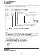
8.02 Figure 8-22 shows a sample SMDR printout
and describes the contents of each column of the
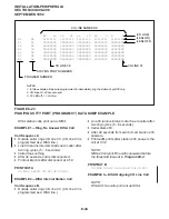
printout. The following examples show several call
record samples and describe the sequence of
events which occurred to generate the call records.
NOTE:
SMDR printout “time of day” and day/month/
year (DD/MM/YY) is the same as the system
clock time/date set by the station connected to
Port 00. SMDR DD/MM/YY will print out each
time 50 call records are generated.
SMDR PRINTOUT EXAMPLES
Direct Inward System Access (DISA) CO Lines
NOTE:
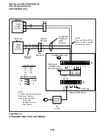
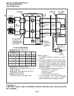
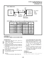
customer-supplied two-way amplifier. In the
example in Figure 8-21, this is CKTA (Central
Office Side A) of the VFR5050.
2) At the MDF, connect the voice pair (VT, VR,
port B) of circuit 3 on the designated PEKU
PCB to the other input of the amplifier. In the
Figure 8-21 example, this is CKTB (subscriber
side B) of VFR5050.
3) Plug the amplifier’s power cord into the 117VAC
(standard) wall outlet.
4) Set the gain and other amplifier parameters
options per the amplifier manufacturer’s in-
stallation documentation.
5) Program the STRATA DK system as follows:
•
Program 10-3: Enables the appropriate
PEKU PCB ports for amplifier connec-
tion. Only enable the ports that will be
connected with the amplifier(s).
•
Program 15-5: Enables appropriate CO
lines for Two-CO line tandem connection.
•
Program 10-1: LEDs 19 and 20 must be
ON.
•
Program 10-2: LED 18 must be ON.
NOTE:
LED 19 in Program 10-1 should be ON if it is
certain that an amplifier will always be avail-
able for two-CO line conference connection
(four maximum, simultaneously). If this LED is
ON and a two-CO line connection is estab-
lished without an external amplifier, the
STRATA DK station may be unbalanced and
receive a hum noise. LED 19 provides addi-
tional station amplification when external am-
plifiers are switched into two-CO line connec-
tions.
8 STATION MESSAGE DETAIL
RECORDING (SMDR) PRINTER/CALL
ACCOUNTING DEVICE OPTIONS
8.00 An SMDR printer or call accounting device
may be connected to the system to provide a hard-
copy record ( Figure 8-22) of station activity. The
STRATA DK system can record incoming, outgo-
Содержание Strata DK 24
Страница 2: ......
Страница 10: ......
Страница 12: ...INSTALLATION SYSTEM DESCRIPTION SECTION 400 096 202 SEPTEMBER 1992 ...
Страница 42: ......
Страница 72: ......
Страница 102: ......
Страница 110: ......
Страница 144: ...INSTALLATION TELEPHONE SECTION 400 096 207 SEPTEMBER 1992 ...
Страница 164: ......
Страница 166: ...INSTALLATION PERIPHERALS SECTION 400 096 208 SEPTEMBER 1992 ...
Страница 170: ......
Страница 238: ...INSTALLATION WIRING DIAGRAMS SECTION 400 096 209 SEPTEMBER 1992 ...
Страница 300: ......
Страница 302: ...REMOTE ADMINISTRATION MAINTENANCE PROCEDURES SECTION 400 096 600 SEPTEMBER 1992 ...
Страница 372: ......


