7-15
INSTALLATION-TELEPHONE
SECTION 400-096-207
SEPTEMBER 1992
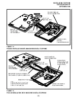
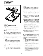
7) Connect the HHEU subassembly wire plug to
the P1 connector on the electronic telephone
PCB (Figure 7-13).
5 DIRECT STATION SELECTION
CONSOLE/SYSTEM CONNECTION
5.01 The system can support up to four Direct
Station Selection consoles with PCTU1, PCTU2,
PCTU3, and PCTU4. (three with PCTUS). There
are two types of consoles: the DDSS console and
the HDSS console. The DDSS console, available
with Release 3 and higher, can be connected to
the last circuit on a PDKU. The HDSS console,
compatible with any release, can be connected to
the last two circuits on a PEKU. This section
provides instructions on how to install both types of
consoles.
5.10 DDSS Console
5.11 DDSS consoles, which can operate with a
digital or electronic telephone (preferably an LCD
model), can connect only to circuit 8 on the PDKU
(via the MDF). Standard twisted single-pair or two-
pair jacketed telephone cable (maximum 1000
feet, 303 meters) is used for the connection. To
accommodate the DDSS console connection, the
instrument end of the cable should be terminated
in a modular station connector block (RJ-11).
Refer to Wiring Diagrams, Section 400-096-209,
for wiring/interconnecting details, including cable
length limitations.
NOTE:
DDSS console cable runs must not have the
following:
•
Cable splits (single or double)
•
Cable bridges (of any length)
•
High resistance or faulty cable splices
CAUTION!
When installing the DDSS cable, do not
run parallel to and within 3 feet of an AC
power line. AC power lines should be
crossed at right (90
°
) angles only. In par-
ticular, avoid running station wire pairs
near devices that generate electrical noise,
such as neon or fluorescent light fixtures.
5.12 DDSS Console Configuration. The follow-
ing considerations should be made when installing
DDSS consoles:
•
DDSS consoles connect only to a PDKU, Circuit
8 only.
•
A maximum of four DDSS consoles can be
installed per system equipped with a PCTU3
and higher.
•
DDSS consoles can operate with an attendant
electronic telephone, as well as with a digital
one.
5.13 DDSS Programming Overview
Program 03
•
Code 64 identifies the PDKU slots that support
DDSS consoles.
Program 28
•
Assigns DDSS console(s) to telephones.
Program 29
•
Assigns button functions for DDSS consoles.
5.20 HDSS Console Connections
5.21 Each HDSS console must be connected to
the data pairs of circuits 7 and 8 on a PEKU (via the
MDF) with standard two-pair twisted, jacketed
telephone cable. To accommodate the connec-
tion, the instrument end of the HDSS console
cable should be terminated in a modular station
connector block (RJ-11). Refer to Wiring Dia-
grams, Section 400-096-209, for wiring/intercon-
necting details. The overall length of the cable run
from the key service unit (KSU) to the HDSS
console must not exceed 500 feet (152 meters), if
using 24 AWG cable. The HDSS console can
operate with either an electronic or digital tele-
phone (preferably an LCD model).
CAUTION!
When installing the HDSS console cable,
do not run parallel to and within 3 feet of an
AC power line. AC power lines should be
crossed at right (90
°
) angles only. Avoid
running HDSS console wire pairs near
devices that generate electrical noise, such
as neon or fluorescent light fixtures.
5.22 HDSS Console Configuration. The follow-
ing considerations should be made when installing
Содержание Strata DK 24
Страница 2: ......
Страница 10: ......
Страница 12: ...INSTALLATION SYSTEM DESCRIPTION SECTION 400 096 202 SEPTEMBER 1992 ...
Страница 42: ......
Страница 72: ......
Страница 102: ......
Страница 110: ......
Страница 144: ...INSTALLATION TELEPHONE SECTION 400 096 207 SEPTEMBER 1992 ...
Страница 164: ......
Страница 166: ...INSTALLATION PERIPHERALS SECTION 400 096 208 SEPTEMBER 1992 ...
Страница 170: ......
Страница 238: ...INSTALLATION WIRING DIAGRAMS SECTION 400 096 209 SEPTEMBER 1992 ...
Страница 300: ......
Страница 302: ...REMOTE ADMINISTRATION MAINTENANCE PROCEDURES SECTION 400 096 600 SEPTEMBER 1992 ...
Страница 372: ......

