3-12
Initial Power-Up Tests
Coral FlexiCom 6000 Installation Manual
Co
mm
on
C
o
nt
ro
l T
est
3
26.
Insert each CLA-ATS card fully into its slot by following steps
to
Connect PI
27.
Attach a Program Interface (PI) device cable to the KB0 programming port
connector on front panel of each MCP-ATS. Verify that the PI device is
configured to match the data rate, word length, parity, and stop bits of KB0.
Default settings for KB0 are 9600bps, 8 data bit, no parity, and 1 stop bit,
respectively.
Supply System Power
28.
Supply power to the Coral system by reversing Step 1 above.
Power OK?
29.
Verify that the PS-ATS units are functioning properly, i.e., the green POWER
indicator on each PS-ATS front panel is illuminated
and
the red FAIL
indicator is off.
Fans OK?
30.
Verify that the fans are working properly. Otherwise, if the fan cage or one of
the fan fuses must be replaced, see
Fan Tray beginning on page 8-15
PI Messages
31.
Verify that the following messages appear on the PI device during system
start-up.
Two separate PI devices are required for the FlexiCom 6000/R - Hot Standby
system. The PI device connected to the MCP-ATS on the right side of the
control shelf is, by default, the
Active
side while the PI Device connected to
the MCP-ATS on the left side of the control shelf is, by default, the
Standby
side. Each side’s messages are received simultaneously and are presented
below.
The version number of the generic feature software is indicated where the x’s
appear in the line that reads “
CCS xx.xx.xx
.”
If the version number shown on the PI device does not match the version
number printed on the CFD disks supplied with the system, perform the
procedure described in
Generic Feature Software beginning on page 4-1
, to install
a new generic software version on the CFD card.
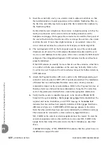
Messages for a Properly Loading Active Side
Loading
...
OMF 80286/80386 LOADER V2.01
Copyright 1992, Tadiran Corporation
Loading /work/k.om8
Loading /work/d.om8
Loading /work/au.om8
Loading /work/p.om8
End Loading File...!
Start Build Checksum
End Build Checksum
Содержание Coral FlexiCom 6000
Страница 2: ......
Страница 4: ......
Страница 18: ......
Страница 28: ...1 10 Introduction Coral FlexiCom 6000 Installation Manual Special Symbols Used in this Document 1 NOTES ...
Страница 32: ......
Страница 51: ...Coral FlexiCom 6000 Installation Manual Hardware Installation Procedure 2 19 Equipment Installation 2 NOTES ...
Страница 80: ...2 48 Hardware Installation Procedure Coral FlexiCom 6000 Installation Manual Equipment Installation 2 4 NOTES ...
Страница 86: ......
Страница 104: ...3 18 Initial Power Up Tests Coral FlexiCom 6000 Installation Manual Common Control Test 3 NOTES ...
Страница 110: ......
Страница 122: ...4 12 Software Installation Procedure Coral FlexiCom 6000 Installation Manual System Database Control 4 NOTES ...
Страница 134: ...4 24 Software Installation Procedure Coral FlexiCom 6000 Installation Manual Upgrading the Coral Version 4 NOTES ...
Страница 143: ...Coral FlexiCom 6000 Installation Manual Chapter 5 External Connections 5 1 External Connections 5 1 ...
Страница 144: ......
Страница 146: ...5 2 External Connections Coral FlexiCom 6000 Installation Manual External Connections 5 NOTES ...
Страница 147: ...Coral FlexiCom 6000 Installation 0DQXDO Chapter 6 Cabinet Descriptions 6 1 Cabinet Descriptions 6 1 ...
Страница 148: ......
Страница 190: ...6 42 Cabinet Descriptions Coral FlexiCom 6000 Installation Manual Cabinet Descriptions 6 NOTES ...
Страница 191: ...Coral FlexiCom 6000 Installation Manual Chapter 7 Power Supplies 7 1 PPS 7 1 7 2 RPS 7 9 7 3 PS ATS 7 19 ...
Страница 192: ......
Страница 210: ...7 18 Power Supplies Coral FlexiCom 6000 Installation Manual RPS Ring Generator Power Supply Unit 7 ...
Страница 224: ......
Страница 322: ...8 98 Common Control Cards Coral FlexiCom 6000 Installation Manual CLA ATS CoraLINK Adapter Card 8 NOTES ...
Страница 338: ...8 114 Common Control Cards Coral FlexiCom 6000 Installation Manual PBD24S Backplane Card 8 NOTES ...
Страница 339: ......


