Coral FlexiCom 6000 Installation Manual
Hardware Installation Procedure
2-25
Eq
uipment Insta
llation
2
RJ-45 I/O Cable Connections (LDF and UDF)
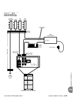
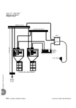
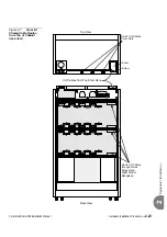
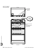
Input/Output (I/O) RJ-45 cables for LAN/WAN/PSTN/router/LTU/CSU/etc. are
routed from above the Coral cabinet through three cable entry points in the rear upper
section of the cabinet. See
Figures
RJ-45 cables routed from the front panel of the peripheral interface cards must be
connected via the LDF or UDF panels. Verify that the RJ-45 cables are not connected
directly from the LAN/WAN/PSTN to the connectors on the front panel of Coral
peripheral cards. Route the cables through the I/O RJ-45 cable entry opening at the
rear top panel of the cabinet.
The LDF (LAN Data Filter) and the UDF (Universal Digital trunk Filter)
incorporate improved RFI immunity. These filters enable the Coral and all
relevant peripheral interface circuits to be fully protected against
radio-frequency interference (RFI) and meet or exceed all requirements and
specifications of telecommunications and electrical safety authorities
world-wide.
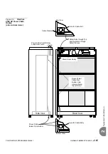
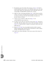
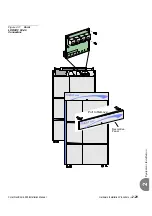
1.
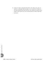
Remove the rear decorative panel nameplate on the top of the cabinet. See
.
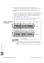
2.
Route the crossover cable (Catalog Number 7244-8000624) from the front
panel of the peripheral cards to the lower connections of the LDF or UDF
panel as shown in
.
3.
Connect one side of the crossover cable routed in
to the RJ-45 jack on
the front panel of the relevant peripheral card.
4.
Connect the other side of the crossover cable routed in
to the lower
) on either the LDF panel or UDF panel, as
follows:
LDF for CLA, PUGW, UGW, UGW-E or IPG peripheral cards
UDF for PRI-23, PRI-30, T1, 30T, or 30TM peripheral cards (layout UDT
or 2DT).
A crossover cable (Catalog Number 7244-8000624) should be used to make this
connection. Otherwise, if an ordinary cable is used, the cards will not be
integrated into the system.
Содержание Coral FlexiCom 6000
Страница 2: ......
Страница 4: ......
Страница 18: ......
Страница 28: ...1 10 Introduction Coral FlexiCom 6000 Installation Manual Special Symbols Used in this Document 1 NOTES ...
Страница 32: ......
Страница 51: ...Coral FlexiCom 6000 Installation Manual Hardware Installation Procedure 2 19 Equipment Installation 2 NOTES ...
Страница 80: ...2 48 Hardware Installation Procedure Coral FlexiCom 6000 Installation Manual Equipment Installation 2 4 NOTES ...
Страница 86: ......
Страница 104: ...3 18 Initial Power Up Tests Coral FlexiCom 6000 Installation Manual Common Control Test 3 NOTES ...
Страница 110: ......
Страница 122: ...4 12 Software Installation Procedure Coral FlexiCom 6000 Installation Manual System Database Control 4 NOTES ...
Страница 134: ...4 24 Software Installation Procedure Coral FlexiCom 6000 Installation Manual Upgrading the Coral Version 4 NOTES ...
Страница 143: ...Coral FlexiCom 6000 Installation Manual Chapter 5 External Connections 5 1 External Connections 5 1 ...
Страница 144: ......
Страница 146: ...5 2 External Connections Coral FlexiCom 6000 Installation Manual External Connections 5 NOTES ...
Страница 147: ...Coral FlexiCom 6000 Installation 0DQXDO Chapter 6 Cabinet Descriptions 6 1 Cabinet Descriptions 6 1 ...
Страница 148: ......
Страница 190: ...6 42 Cabinet Descriptions Coral FlexiCom 6000 Installation Manual Cabinet Descriptions 6 NOTES ...
Страница 191: ...Coral FlexiCom 6000 Installation Manual Chapter 7 Power Supplies 7 1 PPS 7 1 7 2 RPS 7 9 7 3 PS ATS 7 19 ...
Страница 192: ......
Страница 210: ...7 18 Power Supplies Coral FlexiCom 6000 Installation Manual RPS Ring Generator Power Supply Unit 7 ...
Страница 224: ......
Страница 322: ...8 98 Common Control Cards Coral FlexiCom 6000 Installation Manual CLA ATS CoraLINK Adapter Card 8 NOTES ...
Страница 338: ...8 114 Common Control Cards Coral FlexiCom 6000 Installation Manual PBD24S Backplane Card 8 NOTES ...
Страница 339: ......


