Coral FlexiCom 6000 Installation Manual
Common Control Cards
8-103
PB-A
T
S
Peripheral Buffer Unit
8
HDLC and PCM Highways
The PB-ATS card buffers all the signals necessary to provide HDLC highways and
eight six PCM highways for the 512 configuration and 2 PCM highways for the 128
configuration from the 32GC cards to one or two peripheral shelves.
Each of the highways are separately buffered to the backplane with a driver for
insulation between the channels.
The HDLC (control) and PCM (voice) highways are bidirectional, with signals
received from the 32GC card to the peripheral shelf, and similar signals
transmitted from the peripheral shelf back to the 32GC card. The PCM
highways are translated to/from the 4.096 Mbps rates of the peripheral cards
and the 8.192 Mbps rates of the 32GC cards.
Clock and Synchronization Signals
Clock and Synchronization signals are provided by both channels A and B, however,
the PB-ATS selects only one of the channels for a Clock and Sync source to the
peripheral bus via the PB-ATS regardless of from which 32GC they arrive.
A
PB Select line
, controlled by the 32GC card is connected to both of the
PB-ATS cards. This line determines whether Clock and Synchronization for
both peripheral busses are derived from channel A or B, regardless of which
32GC is
Active
. During power up, the PB-ATS in slot 1 is selected to be
Active
. The Active PB-ATS may be switched via the
UNITS
(
Sysgen,5
) branch
in the PI, see Chapter 4 of the relevant
Program Interface & Database
Reference Manual
.
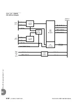
illustrates the PB-ATS circuits in block diagram form.
...................................................................................................
2
Circuit Description
Содержание Coral FlexiCom 6000
Страница 2: ......
Страница 4: ......
Страница 18: ......
Страница 28: ...1 10 Introduction Coral FlexiCom 6000 Installation Manual Special Symbols Used in this Document 1 NOTES ...
Страница 32: ......
Страница 51: ...Coral FlexiCom 6000 Installation Manual Hardware Installation Procedure 2 19 Equipment Installation 2 NOTES ...
Страница 80: ...2 48 Hardware Installation Procedure Coral FlexiCom 6000 Installation Manual Equipment Installation 2 4 NOTES ...
Страница 86: ......
Страница 104: ...3 18 Initial Power Up Tests Coral FlexiCom 6000 Installation Manual Common Control Test 3 NOTES ...
Страница 110: ......
Страница 122: ...4 12 Software Installation Procedure Coral FlexiCom 6000 Installation Manual System Database Control 4 NOTES ...
Страница 134: ...4 24 Software Installation Procedure Coral FlexiCom 6000 Installation Manual Upgrading the Coral Version 4 NOTES ...
Страница 143: ...Coral FlexiCom 6000 Installation Manual Chapter 5 External Connections 5 1 External Connections 5 1 ...
Страница 144: ......
Страница 146: ...5 2 External Connections Coral FlexiCom 6000 Installation Manual External Connections 5 NOTES ...
Страница 147: ...Coral FlexiCom 6000 Installation 0DQXDO Chapter 6 Cabinet Descriptions 6 1 Cabinet Descriptions 6 1 ...
Страница 148: ......
Страница 190: ...6 42 Cabinet Descriptions Coral FlexiCom 6000 Installation Manual Cabinet Descriptions 6 NOTES ...
Страница 191: ...Coral FlexiCom 6000 Installation Manual Chapter 7 Power Supplies 7 1 PPS 7 1 7 2 RPS 7 9 7 3 PS ATS 7 19 ...
Страница 192: ......
Страница 210: ...7 18 Power Supplies Coral FlexiCom 6000 Installation Manual RPS Ring Generator Power Supply Unit 7 ...
Страница 224: ......
Страница 322: ...8 98 Common Control Cards Coral FlexiCom 6000 Installation Manual CLA ATS CoraLINK Adapter Card 8 NOTES ...
Страница 338: ...8 114 Common Control Cards Coral FlexiCom 6000 Installation Manual PBD24S Backplane Card 8 NOTES ...
Страница 339: ......


