Coral FlexiCom 6000 Installation Manual
Hardware Installation Procedure
2-41
Eq
uipment Insta
llation
2
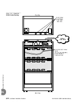
The 32GC is the heart of the Coral FlexiCom 6000 system. A physical connection
must be constructed between the single 32GC or both 32GC cards and each peripheral
shelf, odd or even. The even peripheral shelves must have a hard-wire connection
between the PB-ATS cards and each 32GC card. These connections are implemented
via FC19 cables between the 32GCs piggybacked backplane card, the MPG-ATS and
the PB-ATSs backplane card, the PBD-ATS. The odd shelves make their connection
to the MPG-ATS via a PBD24S (located on the backplane of the odd shelf) connected
to their related PBD-ATSs on the even shelf via FC16 (100cm) or FC18
(50cm discontinued) cables. See
for a wiring schematic.
The arrangement of these connections define the shelf numbering mainly used for the
Programming Interface Updates and Displays. See
Peripheral Shelf Numbering beginning
for shelf numbering descriptions.
Main Cabinets (i.e., cabinets containing a Control Shelf) are shipped with factory
installed cabling between the main cabinet peripheral shelves and the Control Shelf.
The technician is required to wire the peripheral shelves from the other cabinets to the
Control Shelf. The hard wire connections are described below.
...................................................................................................
7
Cabling between the Control and Peripheral Shelves
Содержание Coral FlexiCom 6000
Страница 2: ......
Страница 4: ......
Страница 18: ......
Страница 28: ...1 10 Introduction Coral FlexiCom 6000 Installation Manual Special Symbols Used in this Document 1 NOTES ...
Страница 32: ......
Страница 51: ...Coral FlexiCom 6000 Installation Manual Hardware Installation Procedure 2 19 Equipment Installation 2 NOTES ...
Страница 80: ...2 48 Hardware Installation Procedure Coral FlexiCom 6000 Installation Manual Equipment Installation 2 4 NOTES ...
Страница 86: ......
Страница 104: ...3 18 Initial Power Up Tests Coral FlexiCom 6000 Installation Manual Common Control Test 3 NOTES ...
Страница 110: ......
Страница 122: ...4 12 Software Installation Procedure Coral FlexiCom 6000 Installation Manual System Database Control 4 NOTES ...
Страница 134: ...4 24 Software Installation Procedure Coral FlexiCom 6000 Installation Manual Upgrading the Coral Version 4 NOTES ...
Страница 143: ...Coral FlexiCom 6000 Installation Manual Chapter 5 External Connections 5 1 External Connections 5 1 ...
Страница 144: ......
Страница 146: ...5 2 External Connections Coral FlexiCom 6000 Installation Manual External Connections 5 NOTES ...
Страница 147: ...Coral FlexiCom 6000 Installation 0DQXDO Chapter 6 Cabinet Descriptions 6 1 Cabinet Descriptions 6 1 ...
Страница 148: ......
Страница 190: ...6 42 Cabinet Descriptions Coral FlexiCom 6000 Installation Manual Cabinet Descriptions 6 NOTES ...
Страница 191: ...Coral FlexiCom 6000 Installation Manual Chapter 7 Power Supplies 7 1 PPS 7 1 7 2 RPS 7 9 7 3 PS ATS 7 19 ...
Страница 192: ......
Страница 210: ...7 18 Power Supplies Coral FlexiCom 6000 Installation Manual RPS Ring Generator Power Supply Unit 7 ...
Страница 224: ......
Страница 322: ...8 98 Common Control Cards Coral FlexiCom 6000 Installation Manual CLA ATS CoraLINK Adapter Card 8 NOTES ...
Страница 338: ...8 114 Common Control Cards Coral FlexiCom 6000 Installation Manual PBD24S Backplane Card 8 NOTES ...
Страница 339: ......


