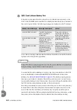
Coral FlexiCom 6000 Installation Manual
Initial Power-Up Tests
3-5
Po
wer S
upply T
est
3
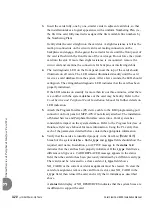
Peripheral Power Supplies (PPS) Test
The following tests must be performed for each PPS unit in the system, see
.
1.
Turn OFF the power switch on the front panel of the PPS.
1.
Insert the PPS power supply completely into its card slot.
2.
Insert at least one Peripheral Interface card (card type is not important) into
any Universal I/O card slot of the respective peripheral shelf.
3.
Turn ON the PPS power switch. Verify that the green Power indicator on its
front panel illuminates.
4.
Insert the negative lead into the +5V (RTN) test point and the positive meter
lead into the +5V (+) test point. Verify that there is approximately 5 volts
between them.
5.
Insert the positive lead into the –5V (RTN) test point and the negative lead
into the –5V (–) test point. Verify that there is approximately 5 volts between
them.
6.
Insert the negative lead of the meter into the +12V (RTN) test point and the
positive lead into the +12V (+) test point. Verify that there is approximately 12
volts between them.
7.
Insert the positive lead into the –12V (RTN) test point and the negative lead
into the –12V (–) test point. Verify that there is approximately 12 volts
between them.
8.
Insert the positive lead of the meter into the –48V (RTN) test point on the
front panel of the PPS. Insert the negative lead of the meter into the –48 (–)
test point. Verify that there is approxi48 volts between the two test
points.
9.
Turn OFF the power switch on the front panel of the PPS.
...................................................................................................
4
Peripheral Shelves Test
Содержание Coral FlexiCom 6000
Страница 2: ......
Страница 4: ......
Страница 18: ......
Страница 28: ...1 10 Introduction Coral FlexiCom 6000 Installation Manual Special Symbols Used in this Document 1 NOTES ...
Страница 32: ......
Страница 51: ...Coral FlexiCom 6000 Installation Manual Hardware Installation Procedure 2 19 Equipment Installation 2 NOTES ...
Страница 80: ...2 48 Hardware Installation Procedure Coral FlexiCom 6000 Installation Manual Equipment Installation 2 4 NOTES ...
Страница 86: ......
Страница 104: ...3 18 Initial Power Up Tests Coral FlexiCom 6000 Installation Manual Common Control Test 3 NOTES ...
Страница 110: ......
Страница 122: ...4 12 Software Installation Procedure Coral FlexiCom 6000 Installation Manual System Database Control 4 NOTES ...
Страница 134: ...4 24 Software Installation Procedure Coral FlexiCom 6000 Installation Manual Upgrading the Coral Version 4 NOTES ...
Страница 143: ...Coral FlexiCom 6000 Installation Manual Chapter 5 External Connections 5 1 External Connections 5 1 ...
Страница 144: ......
Страница 146: ...5 2 External Connections Coral FlexiCom 6000 Installation Manual External Connections 5 NOTES ...
Страница 147: ...Coral FlexiCom 6000 Installation 0DQXDO Chapter 6 Cabinet Descriptions 6 1 Cabinet Descriptions 6 1 ...
Страница 148: ......
Страница 190: ...6 42 Cabinet Descriptions Coral FlexiCom 6000 Installation Manual Cabinet Descriptions 6 NOTES ...
Страница 191: ...Coral FlexiCom 6000 Installation Manual Chapter 7 Power Supplies 7 1 PPS 7 1 7 2 RPS 7 9 7 3 PS ATS 7 19 ...
Страница 192: ......
Страница 210: ...7 18 Power Supplies Coral FlexiCom 6000 Installation Manual RPS Ring Generator Power Supply Unit 7 ...
Страница 224: ......
Страница 322: ...8 98 Common Control Cards Coral FlexiCom 6000 Installation Manual CLA ATS CoraLINK Adapter Card 8 NOTES ...
Страница 338: ...8 114 Common Control Cards Coral FlexiCom 6000 Installation Manual PBD24S Backplane Card 8 NOTES ...
Страница 339: ......


