2-20
Hardware Installation Procedure
Coral FlexiCom 6000 Installation Manual
Eq
uipment Insta
llation
2
Champ Connections
1.
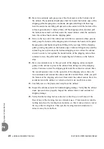
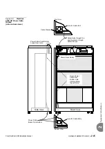
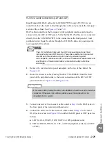
Input/Output (I/O) cables may be routed from above the Coral cabinet through
a cable entry point in the right rear corner (as viewed from the rear) of the
cabinet top, or from below, through a similar entry point in the right rear
corner of the cabinet bottom. Determine whether I/O cables should be routed
from the top or bottom of the cabinet.
If the top entry point is used, release the locking screw, remove the cover plate
and discard it.
If the bottom entry point is used, forcibly remove the cover plate and discard.
2.
Determine the route of I/O cables from the MDF to the connectors on the rear
backplane of the cabinet. Measure the longest distance from an I/O connector
on the backplane to the corresponding cable punch block on the MDF.
3.
Fabricate cables of the length determined above with a male 25 pair connector
on one end, for each I/O connector on the backplane. Thirty two 25 pair cables
are required for a Coral cabinet with 2 peripheral shelves and 48 cables are
required for a Coral cabinet with 3 peripheral shelves.
4.
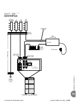
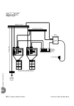
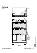
Carefully route the connector end of each I/O cable through the right cable
entry point at the top or bottom of the cabinet, threading the cable through the
guide rings along the right side of the backplane to each I/O connector, as
shown in
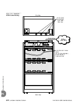
Coral I/O Champ Cable Routes from Bottom of Cabinet (rear view)
and
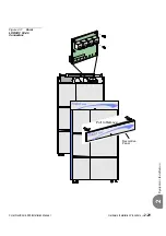
Coral I/O Champ Cable Routes from Top of Cabinet (rear view)
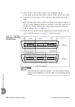
If I/O cables enter the cabinet from the top, route the first cable to the upper
right connector (J37) on the upper peripheral shelf. Insert the cable connector
firmly into the Coral I/O connector. Carefully pull the hook-and-loop fastener
strap tight and press the strap back onto itself, securing the cable connector into
the Coral I/O connector. Route the other end of the cable to the appropriate
cable punch block on the MDF. Repeat this procedure for each I/O cable,
moving from right to left across the upper I/O connectors, and then from right
to left across the lower I/O connectors. When all sixteen I/O cables are installed
on the upper peripheral shelf, move down to the peripheral shelf below, until all
the required I/O cables are in place.
If the I/O cables enter the cabinet from the bottom, route the first cable to the
lower right connector (J38) on the lower peripheral shelf. Insert the cable
...................................................................................................
4
Input/Output (I/O) Cables
Содержание Coral FlexiCom 6000
Страница 2: ......
Страница 4: ......
Страница 18: ......
Страница 28: ...1 10 Introduction Coral FlexiCom 6000 Installation Manual Special Symbols Used in this Document 1 NOTES ...
Страница 32: ......
Страница 51: ...Coral FlexiCom 6000 Installation Manual Hardware Installation Procedure 2 19 Equipment Installation 2 NOTES ...
Страница 80: ...2 48 Hardware Installation Procedure Coral FlexiCom 6000 Installation Manual Equipment Installation 2 4 NOTES ...
Страница 86: ......
Страница 104: ...3 18 Initial Power Up Tests Coral FlexiCom 6000 Installation Manual Common Control Test 3 NOTES ...
Страница 110: ......
Страница 122: ...4 12 Software Installation Procedure Coral FlexiCom 6000 Installation Manual System Database Control 4 NOTES ...
Страница 134: ...4 24 Software Installation Procedure Coral FlexiCom 6000 Installation Manual Upgrading the Coral Version 4 NOTES ...
Страница 143: ...Coral FlexiCom 6000 Installation Manual Chapter 5 External Connections 5 1 External Connections 5 1 ...
Страница 144: ......
Страница 146: ...5 2 External Connections Coral FlexiCom 6000 Installation Manual External Connections 5 NOTES ...
Страница 147: ...Coral FlexiCom 6000 Installation 0DQXDO Chapter 6 Cabinet Descriptions 6 1 Cabinet Descriptions 6 1 ...
Страница 148: ......
Страница 190: ...6 42 Cabinet Descriptions Coral FlexiCom 6000 Installation Manual Cabinet Descriptions 6 NOTES ...
Страница 191: ...Coral FlexiCom 6000 Installation Manual Chapter 7 Power Supplies 7 1 PPS 7 1 7 2 RPS 7 9 7 3 PS ATS 7 19 ...
Страница 192: ......
Страница 210: ...7 18 Power Supplies Coral FlexiCom 6000 Installation Manual RPS Ring Generator Power Supply Unit 7 ...
Страница 224: ......
Страница 322: ...8 98 Common Control Cards Coral FlexiCom 6000 Installation Manual CLA ATS CoraLINK Adapter Card 8 NOTES ...
Страница 338: ...8 114 Common Control Cards Coral FlexiCom 6000 Installation Manual PBD24S Backplane Card 8 NOTES ...
Страница 339: ......


